




-
- PCB TYPE
- PRINTED CIRCUIT BOARD PROTOTYPE ALUMINUM PRINTED CIRCUIT BOARD R&F PCB FPC HIGH FREQUENCY PCB HIGH-TG PCB HEAVY COPPER PCB HDI PCB PCB FOR LIGHTING METAL CORE PCB


time:Jul 20. 2026, 10:58:23
Global electronics Original Equipment Manufacturers (OEMs), automotive hardware designers, and industrial equipment factories face a relentless challenge: how to source circuit boards that guarantee absolute zero-defect reliability while maintaining competitive manufacturing margins. In high-stakes electronic sectors, partnering with an unverified workshop can lead to component trace cracks, poor thermal management, or catastrophic assembly line failures.
To protect production timelines, sophisticated procurement managers are stepping away from low-cost workshops and moving toward strategic partnerships with a certified high quality pcb manufacturer. A top-tier manufacturing partner provides more than just raw fabrication. They deliver robust material tracking, advanced Design for Manufacturability (DFM) support, and highly scalable production capacities that directly boost factory operating yields.
This comprehensive technical guide delivers an engineering-grade roadmap for choosing a production partner. We break down the base material verification rules, advanced automated quality testing systems, layered fabrication tolerances, and commercial supply chain strategies that global OEMs use to optimize their product quality and delivery metrics.
For industrial hardware designers, a high-quality circuit board begins long before a panel enters a chemical etching line. True quality starts with rigorous material verification. A reputable high quality pcb manufacturer uses specialized, traceable laminates to ensure consistent electrical insulation and mechanical strength.
Low-cost workshops frequently use unbranded, low-grade copper-clad laminates (CCL) that suffer from internal micro-voids or uneven fiberglass weaves. Under thermal stress, these sub-standard matrices outgas, leading to devastating trace delamination and layer separation.
An elite manufacturing facility utilizes verified, tier-one materials like Kingboard, Isola, or Rogers. These premium substrates offer predictable physical and electrical properties:
Glass Transition Temperature (Tg): Maintaining standard baselines at or above 150 to 180 degrees C to ensure absolute structural stability during high-temperature, lead-free reflow soldering cycles.
Coefficient of Thermal Expansion (CTE): Restricting z-axis expansion rates to under 3.0 percent to prevent stress fractures on fine-pitch plated through-holes.
Consistent current delivery relies on high-purity, uniform copper foil distribution. Premium manufacturers maintain strict standards for copper electroplating, ensuring a minimum wall thickness of 20 to 25 um inside all plated through-holes (PTH). This heavy plating reinforces the via barrels against mechanical cracks and handles large power spikes without overheating.
Achieving stable production yields across high-volume factory runs requires shifting from manual inspection to fully automated quality control systems. A true high quality pcb manufacturer implements multi-layered inspection points throughout the assembly workflow.
Manual visual inspection cannot reliably catch sub-mil micro-cracks or slight trace necking on complex layouts. Modern production lines utilize high-resolution 3D AOI scanners after the etching process. These automated systems compare the physical copper traces on the panel against the original Gerber design files in real time, catching shorts, opens, and trace irregularities down to 2 mils.
Every multi-layer board must pass complete electrical continuity testing before delivery. While traditional fixture testing is suitable for simple, massive runs, a versatile high quality pcb manufacturer utilizes advanced flying probe testing equipment for high-density, complex boards. These computer-guided probes rapidly check for continuity, shorts, and specific controlled impedance metrics across tight-pitch nets without damaging delicate surface pads.
For high-density, multi-layer stackups with blind and buried vias, standard visual or optical tools cannot inspect internal layers. Automated X-ray inspection allows quality control teams to look through the composite layers. AXI checks internal via registration alignment, verifies multi-layer copper adhesion, and inspects internal solder joints for voiding or micro-bridging.
As consumer and industrial electronics contract into tighter form factors, circuit designs require finer pitch geometries and tighter manufacturing tolerances. To handle these advanced requirements, electronics brands prioritize vendors with sophisticated fabrication capabilities.
Standard consumer devices use wide 6-mil lines, but industrial controls, medical hardware, and telecommunication systems demand high-density interconnect (HDI) capabilities. A premier manufacturer utilizes direct laser imaging (LDI) rather than traditional film exposure to consistently execute ultra-fine trace widths and spaces down to 3 mils (0.075 mm).
High-speed digital signaling—such as USB 4.0, PCIe Gen 5, and high-frequency RF networks—demands strict controlled impedance matching. A high-quality production facility uses advanced polar impedance design tools to manage trace width, dielectric layer thickness, and copper heights. This level of control ensures tight tolerances within plus or minus 5 to 10 percent, protecting signal integrity and preventing data losses.
| Manufacturing Metric | Low-Cost Prototype Workshop | High Quality Manufacturer Capability | Engineering Advantage for Procurement |
| Minimum Trace Width/Space | 5 to 6 mils (0.127 mm) | Down to 3 mils (0.075 mm) | Supports ultra-dense layout designs and micro-SMD configurations. |
| Via Hole Size Tolerance | plus or minus 3 mils (0.075 mm) | plus or minus 1 mil (0.025 mm) | Prevents breakout issues on small annular rings and tight via pitches. |
| Layer-to-Layer Registration | 4 to 5 mils (0.100 mm) | Less than 1.5 mils (0.038 mm) | Guarantees internal alignment across complex multi-layer stackups. |
| Impedance Tolerance | plus or minus 15 to 20 percent | plus or minus 5 to 10 percent | Eliminates signal degradation in high-speed digital networks. |
| Solder Mask Registration | 3 mils (0.075 mm) | 1 mil (0.025 mm) | Prevents solder bridging on fine-pitch BGA pad layouts. |
For a complete breakdown of global sourcing strategies, near-source logistics benefits, and high-reliability turnkey assembly options, read our industry briefing on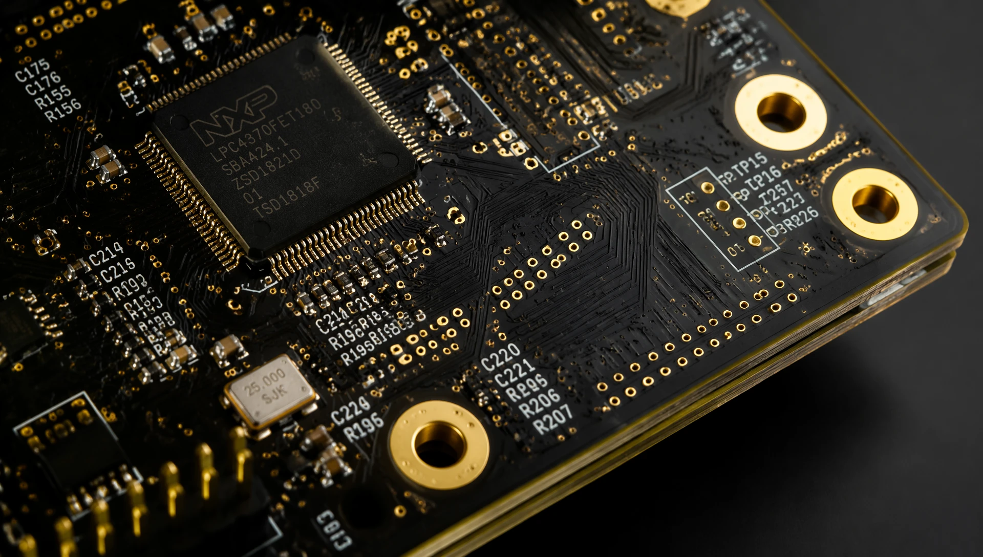
A major source of production delays and component losses in volume manufacturing stems from unresolved layout discrepancies in the original Gerber files. An expert manufacturing partner acts as a proactive technical advisor, running complete Design for Manufacturability (DFM) check routines before building tooling fixtures.
During the engineering verification phase, an expert factory review team analyzes your board layout to catch common manufacturing liabilities:
Acid Traps: Identifying tight, acute-angle trace junctions where chemical etchants can pool during processing. This pooling can over-etch the circuit path and cause open-circuit failures in the field.
Copper Slivers: Catching thin, narrow wedges of copper or solder mask insulation. These slivers can peel off during volume processing and land across exposed conductors, causing intermittent electrical shorts.
Annular Ring Integrity: Verifying that the copper pads surrounding drilled holes offer sufficient area to handle drilling deviations without causing pad breakouts.
By resolving these layout anomalies during the pre-production phase, factories can avoid expensive re-tooling fees, optimize material utilization, and secure high yields on high-volume production runs.
From a supply chain standpoint, choosing a production partner involves evaluating total lifecycle costs alongside material quality. Managing complex projects across separate fabricators, component brokers, and assembly houses introduces supply chain risks, tracking issues, and unexpected production delays.
Transitioning to an integrated single-source supplier provides major operational advantages:
Faster Lead Times: Keeping raw fabrication and automated surface mount technology (SMT) component assembly within a unified facility eliminates transit times between vendors. This can accelerate delivery speeds by 5 to 7 production days.
Unified Quality Tracking: If a component positioning or pad layout error occurs during SMT setup, a single engineering team resolves it immediately. This avoids finger-pointing between separate board shops and assembly houses.
Lower Procurement Costs: Bundling raw materials, stencil creation, board fabrication, and automated assembly helps procurement managers reduce freight handling costs and maximize volume discounts.
To review our complete range of layer stackup selections, specialized surface finishes, and automated precision fabrication capabilities, explore our production overview at the
For global OEMs shipping products into heavily regulated markets like North America, Europe, and Japan, regulatory compliance is non-negotiable. A premium manufacturing facility maintains verified compliance with major international environmental and safety standards.
ISO 9001:2015: Proves the facility operates under an audited, structured quality management system that guarantees consistent material tracking and continuous process optimization.
UL 796 Recognition: Ensures all manufactured substrates meet international flammability safety guidelines (UL 94 V-0), which is mandatory for consumer appliances and industrial power systems.
RoHS and REACH Compliance: Verifies that all laminates, solder mask coatings, and surface finishes (such as Lead-Free HASL, ENIG, or OSP) are free from restricted hazardous substances. This ensures smooth customs clearance into European markets.
Securing reliable, high-yield electronics manufacturing requires an experienced manufacturing partner. As a fully certified, high-capability high quality pcb manufacturer, ApolloPCB manages every phase of the circuit board fabrication and assembly pipeline.
Our advanced facility is equipped with automated laser direct imaging (LDI), high-resolution 3D AOI testing platforms, and precision multi-stage lamination systems. This allows us to handle complex projects—from standard double-sided layouts to high-density, multi-layer HDI boards—while maintaining strict dimensional tolerances.
We stock premium brand laminates and maintain high environmental standards to ensure your industrial controls, automotive modules, and medical devices deliver consistent, long-term performance in the field.
Ready to improve your production yields, eliminate component sourcing bottlenecks, and secure stable delivery times for your business? Visit our dedicated
Premium manufacturing facilities utilize automated layer-to-layer registration alignment systems along with post-etch punch equipment. Before lamination, inner layers are optically scanned and mechanically locked into place. This process limits layer-to-layer shifting to less than 1.5 mils, ensuring precise alignment for mechanical or laser drilling routines.
Electroless Nickel Immersion Gold (ENIG) provides a completely flat, co-planar surface finish that is ideal for fine-pitch surface mount devices (SMD) and ball grid arrays (BGA). Unlike traditional Hot Air Solder Leveling (HASL), which can leave uneven solder mounds, ENIG delivers excellent shelf life, high oxidation resistance, and superior thermal durability for industrial electronics.
Running an automated Design for Manufacturability (DFM) verification check allows engineering teams to catch layout liabilities like copper slivers, acid traps, and insufficient annular rings before building physical tooling. Resolving these anomalies early prevents expensive re-work loops, reduces material waste, and guarantees high production yields from the very first run.

Got project ready to assembly? Contact us: info@apollopcb.com



 Whatsapp 0086 755 29438407
 Mail info@apollopcb.com
 Tel 0086 755 29438407


ABOUT US

PRODUCTS
TECHNOLOGY
KNOWLEDGE CENTRE
CULTURE
NEWS
We're not around but we still want to hear from you! Leave us a note:

Leave Message to APOLLOPCB
