-
- PCB TYPE
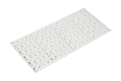
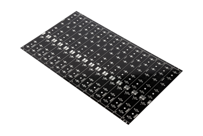
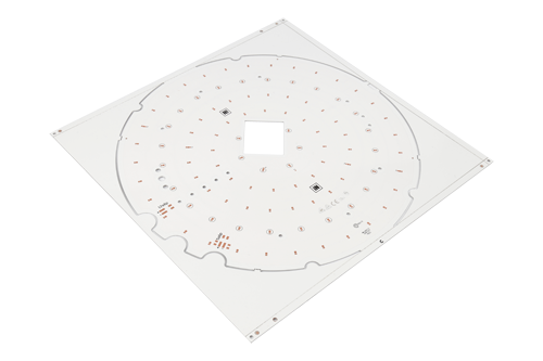
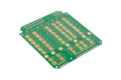
- PRINTED CIRCUIT BOARD PROTOTYPE ALUMINUM PRINTED CIRCUIT BOARD R&F PCB FPC HIGH FREQUENCY PCB HIGH-TG PCB HEAVY COPPER PCB HDI PCB PCB FOR LIGHTING METAL CORE PCB
Real PCB &PCB Assembly Manufacturer
IS09001:2015 Standard
UL.RoHS. REACH Certified
3000+ Orders/Day
99% on-time Shipping
100,000+ Customers
| No. | Item | Manufacturing Capabilities | Illustration |
|---|---|---|---|
| 1 | Material | FR-4 (Fiberglass) | For Rogers, Taconic, ARLON and other HDI boards, please contact APOLLOPCB for details. |
| 2 | Number of Layers | 1 Layer, 2 Layers, 4 Layers, 6 Layer, 8 Layers, 10 Layers | Standard stackup for multilayer pcbs. |
| 3 | TG Grade | TG130~140, TG150~160, TG170~180 | |
| 4 | Max PCB Size | 1 layer & 2 layers: 1200*300mm or 600*500mm Multi-layers: 600*500mm | |
| 5 | Min PCB Size | 5mm*5mm | |
| 6 | Board Size Tolerance(Outline) | ±0.2mm(CNC routing) ±0.5mm(V-scoring) | |
| 7 | Surface Finish | HASL with lead, HASL lead free, Immersion gold(ENIG), OSP, Hard gold, ENEPIG, Immersion silver (Ag), None |
|
| 8 | Board Thickness | 1 Layer/2 Layers: 0.2~2.4mm 4 Layers: 0.4~2.4mm 6 Layers: 0.8~2.4mm 8 Layers: 1.0~2.4mm 10 Layers: 1.2~2.4mm
Note: Customized PCB thickness and Layer stackup are acceptable. | |
| 9 | Board Thickness Tolerance | Thickness≥1.0mm: ±10% Thickness<1.0mm: ±0.1mm
Note: Normally “+ Tolerance” will occur due to PCB processing steps such as electroless copper, solder mask and other types of finish on the surface. | |
| 10 | Outer Layer Copper Thickness | 1oz/2oz/3oz (35μm/70μm/105μm)
Note: 2oz PCB thickness≥1.2mm, Via size≥0.25mm, Min Track/Spacing≥0.15mm
3oz PCB thickness≥2.0mm, Via size≥0.3mm, Min Track/Spacing≥0.2mm |
|
| 11 | Inner Layer Copper Thickness | 1oz/1.5oz (35μm/50μm) | |
| 12 | Outer layer Min track/spacing | ≥3mil |
|
| 13 | Inner layer Min track/spacing | ≥4mil | |
| 14 | Annual ring size | ≥0.13mm | |
| 15 | Grid Line track/spacing | ≥0.2mm |
|
| 16 | Coil board Line track/spacing | ≥0.2mm |
|
| 17 | BGA pad size | ≥0.2mm |
|
| 18 | BGA Distance | ≥0.12mm | |
| 19 | Board Outlines | Track to Outline: ≥0.3mm Trace to V-cut line: ≥0.4mm |
|
| 20 | Finished Hole Size Tolerance | ±0.08mm |
|
| 21 | Finished Hole Diameter(CNC) | 0.2mm~6.3mm
1. PCB Thickness=2.0mm, Min hole size is 0.3mm 2. PCB Thickness=2.4mm, Min hole size is 0.4mm 3. Copper Thickness=2OZ, Min hole size is 0.25mm 4. Copper Thickness=3OZ, Min hole size is 0.3mm | |
| 22 | TH Via Distance | Equipotential: 0.15mm Isoelectric: 0.25mm | |
| 23 | Plated Slot Size | ≥0.5mm
Note: L:W=2.5: 1 (Should be 2.5:1 or higher. If it is less than this, the holes may be misaligned.) If you can't draw a long hole in your design, you can draw a continuous round hole and it will be regarded as a long hole. Also, it is okay to draw the oblong hole in Profile Layer instead of Drilling Layer. |
|
| 24 | Castellated Holes | ≥0.6mm |
|
| 25 | Non-Plated Holes | ≥0.8mm |
|
| 26 | NPTH to Copper Line | ≥0.2mm | |
| 27 | Soldermask | Green, Red, Yellow, White, Black, Blue, Purple, Matte Green,Matte Black,None |
|
| 28 | Soldermask Thickness | 20~30um | |
| 29 | Soldermask Bridge | Green: ≥0.1mm Others: ≥0.15mm |
|
| 30 | Soldermask to soldering pad distance | ≥0.05mm | |
| 31 | Silkscreen | White, Black, Yellow, None |
|
| 32 | Minimum Character Width(Legend) | ≥0.15mm
Note: Characters of less than 0.15mm wide will be too narrow to be identifiable. | |
| 33 | Minimum Character Height (Legend) | ≥0.75mm
Note: Characters of less than 0.8mm high will be too small to be recognizable. | |
| 34 | Character Width to Height Ratio (Legend) | 1: 5 (In PCB silkscreen legends processing, 1:5 is the most suitable ratio) | |
| 35 | Silkscreen to Soldermask Distance | ≥0.1mm | |
| 36 | V-cut Line | ≥75mm
Note: PCB thickness≥0.6mm Details refer to right side picture |
|
| 37 | V-cut Line Distance | ≥3.5mm |
|
| 38 | Distance betwen Board to Board | ≥0.8mm |
|
| 39 | Stamp-hole Width | ≥2.0mm
Note: PCB size and thickness are subject to review by APOLLOPCB. | |
| 40 | Tab-route Width | ≥1.6mm
Note: PCB size and thickness are subject to review by APOLLOPCB. | |
| 41 | Edge Rail | ≥3.5mm
Note: If choosing panel by APOLLOPCB, we will add 5mm edge rails on both sides by default. |
|
| 42 | Gold Finger | Bevelling Angle: 30~45° Depth: ≥1mm Length: 45mm~280mm
Note: Board thickness≥1.2mm |
|
| 43 | Special Specification | Impedance control Custom Layer Stackup Interstitial Via Hole(IVH) Via in pad Via filled with resin Countersinks/Counterbores Carbon Mask Halogen-Free Z-axis milling Edge Plating Others |
|

Got project ready to assembly? Contact us: info@apollopcb.com


 Whatsapp 0086 755 29438407
 Mail info@apollopcb.com
 Tel 0086 755 29438407


ABOUT US

PRODUCTS
TECHNOLOGY
KNOWLEDGE CENTRE
CULTURE
NEWS
We're not around but we still want to hear from you! Leave us a note:

Leave Message to APOLLOPCB