




-
- PCB TYPE
- PRINTED CIRCUIT BOARD PROTOTYPE ALUMINUM PRINTED CIRCUIT BOARD R&F PCB FPC HIGH FREQUENCY PCB HIGH-TG PCB HEAVY COPPER PCB HDI PCB PCB FOR LIGHTING METAL CORE PCB


time:Jul 15. 2026, 14:41:07
In the hyper-competitive electronics manufacturing landscape, global Original Equipment Manufacturers (OEMs) and procurement managers face a constant challenge: balancing optimal structural reliability with rigorous cost control. While FR4 remains the default choice for many printed circuit board layouts, it often introduces unnecessary cost overhead for mid-tier industrial controls, LED drivers, and consumer power supplies.
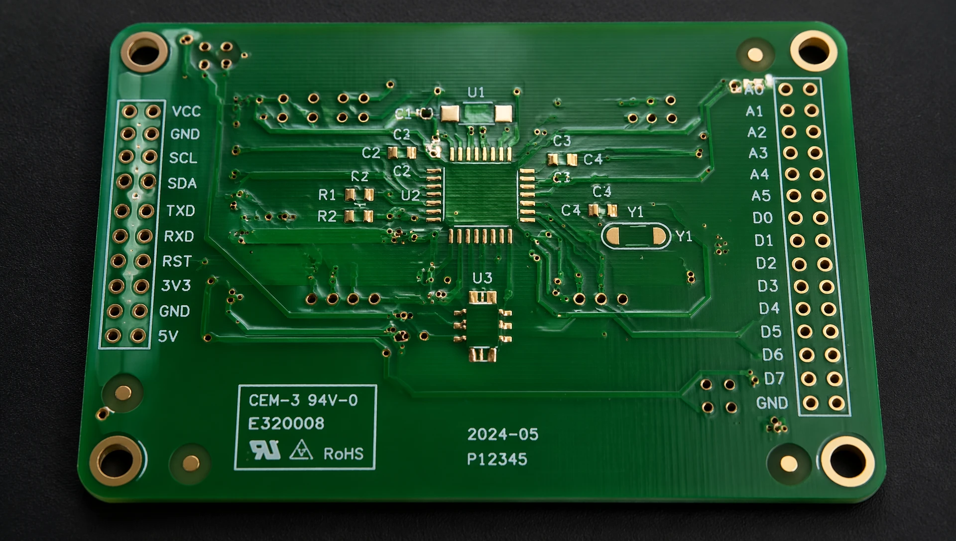
This is where the cem3 pcb becomes a strategic alternative. Serving as a cost-effective, drop-in replacement for FR4 in specific applications, this composite substrate delivers comparable mechanical properties and electrical insulation at a lower material cost.
This comprehensive technical guide provides an engineering evaluation of composite epoxy material grade 3 (CEM-3). We break down base material properties, advanced mechanical drilling tolerances, thermal optimization, and commercial procurement metrics that global electronics factories leverage to optimize production yields.
To understand the operational benefits of a cem3 pcb, one must analyze its internal material composition. Unlike standard FR4, which utilizes multiple layers of woven fiberglass cloth impregnated with epoxy resin, CEM-3 features a hybrid, composite core structure.
A standard cem3 pcb material is structured using three distinct zones:
Surface Layers: The top and bottom exterior faces are composed of woven fiberglass cloth, identical to the fabric utilized in FR4. This ensures smooth surface finishes, reliable copper foil adhesion, and excellent compatibility with standard chemical etching and solder mask applications.
Central Core: The interior layer consists of a non-woven, chopped glass fiber fleece (often termed glass mat paper) impregnated with epoxy resin.
Resin Fillers: Advanced laminates mix specialized inorganic crystalline fillers (such as aluminum hydroxide or silica compounds) into the core resin matrix to enhance flame retardancy, mechanical stability, and thermal dissipation.
By replacing the inner layers of woven fabric with a non-woven glass mat, laminate manufacturers reduce overall material processing costs. This structural shift makes raw CEM-3 panels significantly easier to punch, rout, and drill, which translates to reduced tool wear on factory floor CNC lines.
For hardware engineers designing ruggedized power electronics or high-volume appliances, component reliability depends heavily on base laminate parameters. When reviewing a cem3 pcb material tg130 datasheet, it is essential to look at how these specifications match up against industrial requirements.
| Property Parameter | Standard CEM-3 Laminate | Standard FR-4 Laminate | Engineering Implications for Factories |
| Glass Transition Temp (Tg) | 130 to 140 degrees C | 135 to 140 degrees C | Identical operational performance up to standard assembly thresholds. |
| Thermal Conductivity | 0.25 to 0.40 W/m-K | 0.20 to 0.30 W/m-K | CEM-3 frequently displays superior thermal dissipation due to core fillers. |
| Dielectric Constant (Dk at 1MHz) | 4.6 to 4.8 | 4.5 to 4.7 | Minimal variance; fully suitable for power supply and low-frequency signaling. |
| Dissipation Factor (Df at 1MHz) | 0.020 to 0.025 | 0.015 to 0.020 | Slightly higher loss tangent; not recommended for ultra-high-frequency RF designs. |
| Flexural Strength (MPa) | 350 to 400 | 450 to 500 | FR4 is stiffer, but CEM-3 provides excellent elasticity, preventing impact cracks. |
| Flammability Rating | UL 94 V-0 | UL 94 V-0 | Complies with international safety regulations for commercial electronics. |
For a deeper dive into how these material properties interact under sustained thermal stress, read our comprehensive
Standard CEM-3 handles general electronics well, but automotive assemblies, industrial power switches, and dense LED arrays demand enhanced thermal metrics. Driven by these needs, laminate manufacturers developed specialized high-performance composite variations.
Within the industrial supply chain, Kingboard's kb7150t cem3 pcb series stands out as a highly requested benchmark. Traditional composite materials exhibit lower z-axis thermal expansion, but specialized options like KB7150T are formulated to mitigate this issue.
By integrating a high-density ceramic filler within the non-woven glass mat core, this material achieves a high thermal cem3 pcb substrate status. It delivers enhanced dimensional stability during lead-free reflow cycles, preventing pad delamination and via cracking in multi-layered, single-sided, or double-sided layouts.
When looking at high-specification applications, you will often encounter designations like cem-3-09ht cem3 pcb formulations. The "HT" suffix stands for High Temperature, indicating an optimized resin system that exhibits superior resistance to thermal degradation.
Furthermore, using a dedicated thermal conductive cem3 pcb material helps bridge the performance gap between traditional FR4 and expensive aluminum-clad insulated metal substrates (IMS). It offers a balance of reliable electrical isolation with enhanced, passive planar heat dissipation.
Factory Procurement Note: If your design features tightly grouped power MOSFETs or high-lumen surface-mount LEDs, selecting a specialized thermal composite panel can reduce junction temperatures by up to 8 to 12 degrees C compared to baseline FR4. This can eliminate the need for secondary aluminum heat sinks.
One of the key manufacturing advantages of a cem3 pcb is its superior machinability. Because the central core features chopped glass fleece rather than dense, woven glass bundles, CNC routing bits and mechanical drill pins encounter less resistance. This characteristic allows factory production teams to execute complex mechanical features with tight tolerances.
A countersink hole features a conical, beveled edge designed to allow flat-head screws or fasteners to sit flush with or below the laminate surface.
Manufacturing Challenge: In standard FR4, mechanical countersinking can cause micro-delamination along the woven glass weave layers, leading to frayed edges and unraveled fibers.
The CEM-3 Advantage: Executing countersink holes in cem3 pcb processing results in smooth, clean beveled walls. The chopped glass fibers shear cleanly without separating from the epoxy matrix, ensuring uniform load distribution when torque is applied to mounting fasteners.
A counterbore hole features a flat-bottomed cylindrical enlargement above a smaller pilot hole. It is typically used to seat socket head cap screws or hex bolts within the board profile.
Depth Control Tolerances: Creating precise counterbore holes in cem3 pcb configurations demands rigid depth control (Z-axis accuracy within plus or minus 0.05 mm).
Tool Wear Benefits: Because the composite core material is significantly less abrasive than woven fiberglass, CNC cutting edges retain their sharpness up to 40 percent longer. This reduction in tool wear minimizes exit burrs and ensures the bottom surface of the counterbore remains flat and parallel to the PCB surface.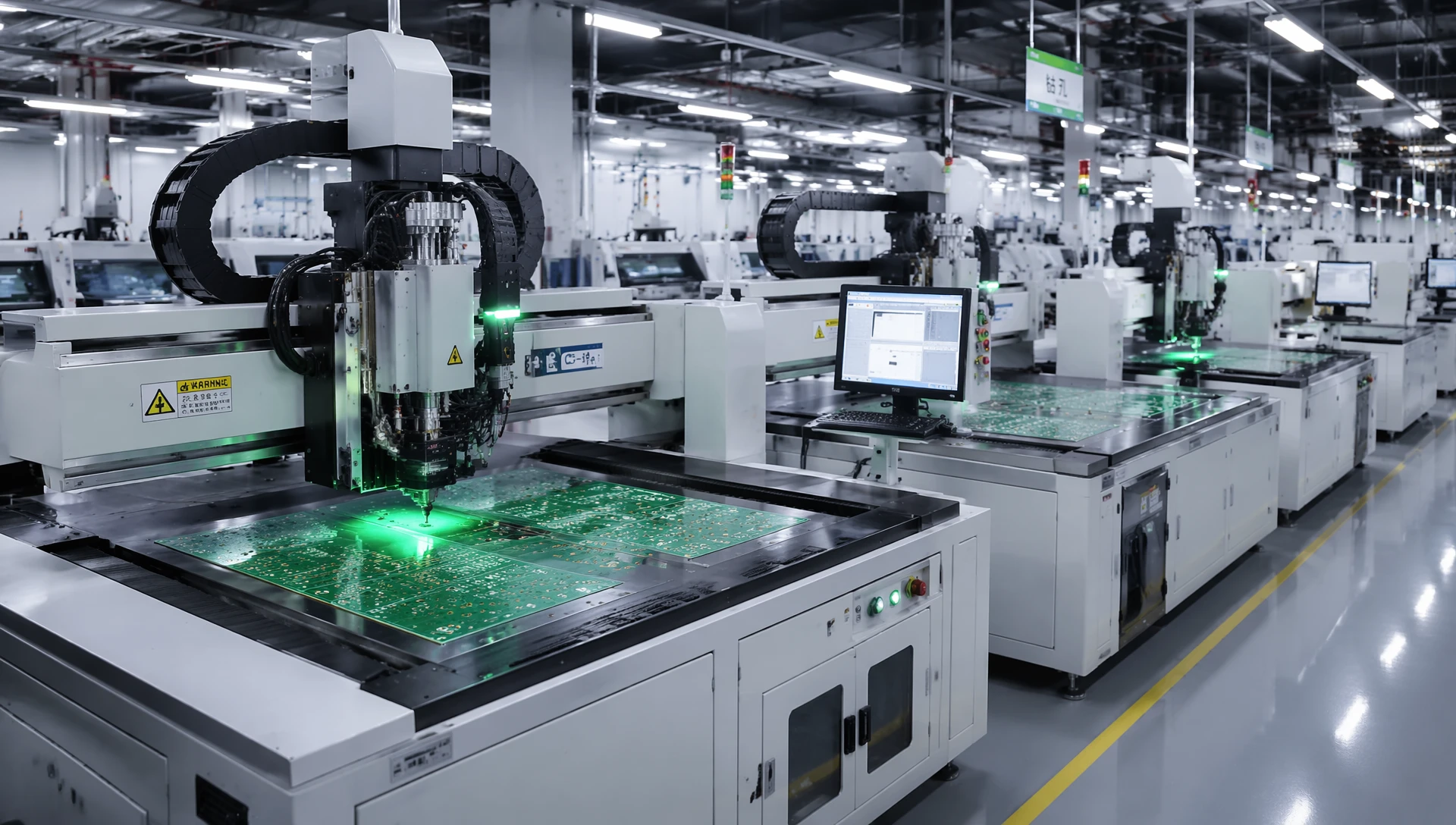
When engineering a circuit board using a cem3 pcb substrate, implementing strict Design for Manufacturability (DFM) guidelines ensures high production yields.
Because the composite glass core has a slightly different thermal contraction profile than woven glass cloth, keep these layout variables in mind during the Gerber design phase:
Solder Mask Openings: Maintain a minimum expansion clearance of 2 mils (0.05 mm) around all SMT pad patterns to accommodate minor shifting during thermal cycles.
Trace Geometries: Keep minimum line widths and track spacings at or above 5 mils (0.127 mm) for standard production runs. For fine-line layouts, consult with an engineering partner ahead of fabrication.
For double-sided layouts, plated through-hole (PTH) integrity depends on aspect ratio control:
Limit your mechanical drill aspect ratio (board thickness divided by drill diameter) to 8 to 1.
Ensure that all through-hole via pads include a minimum outer annular ring of 5 mils to prevent pad breakout during mechanical drilling routines.
To review sample board stacks, surface finishes, and specific fabrication pad templates, read our technical brief on
From a corporate procurement standpoint, choosing a cem3 pcb layout is driven by strategic cost reduction. For simple single-sided or double-sided layouts that do not route high-frequency RF signals, substituting FR4 with CEM-3 can reduce raw base material costs by roughly 10 percent to 15 percent.
Global contract electronics factories prioritize CEM-3 integration across several main product categories:
LED Solid-State Lighting: Commercial LED tubes, backlight panels, architectural light bars, and automotive internal instrumentation modules.
Power Supplies & Conversion: AC-to-DC switching power supplies, industrial transformers, smart meters, and battery charging stations.
Appliance Controller Boards: Control sub-assemblies for washing machines, HVAC systems, refrigerators, and automated industrial sensor housings.
For an analytical breakdown of high-frequency signal propagation, dielectric performance, and long-term mechanical durability comparisons, check out our engineering guide on
Maximizing the mechanical and thermal advantages of composite materials requires an experienced fabrication partner. As an established, certified kb7150t cem3 pcb manufacturer, ApolloPCB maintains complete control over composite processing workflows.
Our factory floor is equipped with specialized CNC drill bits, real-time depth-monitored router systems, and advanced vacuum lamination presses. These technologies ensure that every mechanical feature—from complex flat-bottom counterbores to tight-pitch plated through holes—meets strict international tolerances.
We stock premium Kingboard substrates and high-thermal conductive composite materials to guarantee that your high-volume production runs remain insulated from raw material supply bottlenecks.
Ready to lower your manufacturing overhead and secure stable material routing for your next project? Browse our dedicated

While CEM-3 is highly optimized for single-sided and double-sided layouts, advanced fabrication facilities can manufacture stable 4-layer configurations. For complex multi-layer designs exceeding 4 layers, standard FR4 or high-Tg materials are recommended to maintain z-axis dimensional stability and prevent internal layer shifting during high-temperature reflow processing.
Kingboard KB7150T is engineered with specialized inorganic ceramic fillers distributed within its composite core resin matrix. This modification significantly improves thermal conductivity and provides a lower coefficient of thermal expansion (CTE) compared to standard composite boards. This makes it an excellent choice for automotive electronics and high-power industrial control boards.
CEM-3 exhibits exceptional punching and routing properties due to its non-woven chopped glass fleece core. When processing board shapes or large cutouts, standard FR4 can cause heavy tool wear and edge fraying from its dense woven glass layers. In contrast, CEM-3 breaks cleanly, allowing for smooth mechanical profiles, extended machine tool lifespans, and cleaner edges.

Got project ready to assembly? Contact us: info@apollopcb.com



 Whatsapp 0086 755 29438407
 Mail info@apollopcb.com
 Tel 0086 755 29438407


ABOUT US

PRODUCTS
TECHNOLOGY
KNOWLEDGE CENTRE
CULTURE
NEWS
We're not around but we still want to hear from you! Leave us a note:

Leave Message to APOLLOPCB
