




-
- PCB TYPE
- PRINTED CIRCUIT BOARD PROTOTYPE ALUMINUM PRINTED CIRCUIT BOARD R&F PCB FPC HIGH FREQUENCY PCB HIGH-TG PCB HEAVY COPPER PCB HDI PCB PCB FOR LIGHTING METAL CORE PCB


time:Aug 06. 2026, 16:31:44
Modern medical wearables, automotive displays, robotics joints, and aerospace avionics demand reliable interconnect solutions within constrained spatial footprints. Traditional rigid circuit boards, constrained by fixed geometries and bulky wire harnesses, cannot fulfill the weight, dynamic bending, and multi-planar routing requirements of modern compact devices.
Partnering with an experienced provider of fpc fabrication services bridges the gap between complex electrical architecture and physical space constraints. Flexible Printed Circuits (FPCs) leverage ultra-thin polyimide substrates, rolled-annealed copper foil, and high-performance coverlays to deliver dynamic flexure capabilities, reduced harness weight by up to 70 percent, and enhanced signal integrity.
This engineering guide examines every stage of high-precision flex circuit production. We detail polyimide substrate selection, dynamic bend radius calculations, coverlay lamination, rigid-flex integration, and Design for Manufacturability (DFM) rules that enable global OEMs to maximize manufacturing yields and lower total lifecycle costs.
Flexible Printed Circuit (FPC) manufacturing differs fundamentally from standard rigid FR-4 processing. FPCs utilize thin, flexible dielectric films that withstand millions of dynamic bending cycles without electrical failure or copper trace delamination.
An industrial flex circuit consists of three functional elements:
The Polyimide (PI) Base Film: A thermally stable polymer substrate offering excellent dielectric strength, low outgassing, and high resistance to reflow soldering temperatures up to 260°C.
Rolled-Annealed (RA) Copper Foil: Unlike electro-deposited (ED) copper used in rigid boards, RA copper features elongated horizontal grain structures engineered to absorb continuous mechanical stress without fatigue cracking.
Polyimide Coverlay: A protective insulation layer laminated over etched copper traces, replacing traditional brittle solder mask resins to maintain outer layer flexibility and moisture sealing.
Weight and Volume Reduction: Replacing conventional wire harnesses with custom flexible circuits reduces assembly weight by up to 70% and spatial footprint by up to 60%.
Dynamic Bend Durability: High-grade RA copper formulations withstand over 100,000 to 1,000,000 dynamic flex cycles when designed according to IPC-2223 bend radius standards.
Simplified Assembly Workflows: Integrated stiffeners, connector pads, and direct surface-mount technology (SMT) compatibility eliminate wiring installation errors and shorten line assembly times.
For a detailed review of high-density flexible circuit capabilities and stackup configurations, explore our technical breakdown on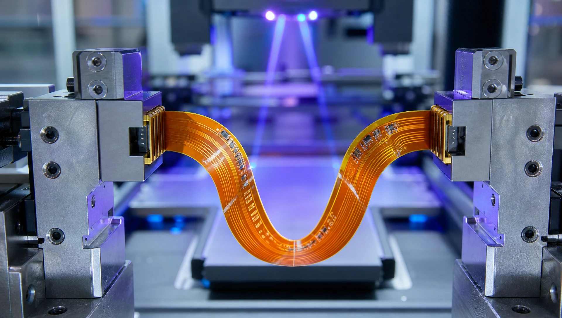
Selecting the proper base material stackup directly impacts circuit thickness, signal integrity, and long-term thermal endurance.
Flex circuit laminates are categorized by how the copper foil is bonded to the polyimide core film:
Adhesive-Based (3-Layer) Laminates: Utilize acrylic or epoxy adhesives to bond copper foil to the polyimide base. While cost-effective for simple static bending applications, acrylic adhesives exhibit higher thermal expansion coefficients, lower thermal conductivity, and reduced flexibility.
Adhesiveless (2-Layer) Laminates: Cast copper directly onto the polyimide film without an intermediate adhesive layer. Adhesiveless laminates offer thinner overall profiles, superior thermal dissipation, higher dielectric breakdown voltage, and improved dimensional stability for fine-pitch component assembly.
| Material Characteristic | 2-Layer Adhesiveless PI | 3-Layer Adhesive-Based PI | Polyester (PET) Film |
| Base Substrate Thickness | 12.5 µm - 25 µm | 25 µm - 50 µm | 50 µm - 125 µm |
| Operating Temp Range | -200°C to +260°C | -40°C to +105°C | -20°C to +85°C |
| Thermal Conductivity | 0.25 - 0.35 W/m·K | 0.12 - 0.18 W/m·K | 0.15 W/m·K |
| Dynamic Bend Radius | Superior (R >= 6x thickness) | Moderate (R >= 10x thickness) | Poor (Static Flex Only) |
| Reflow Solder Resistance | 260°C Lead-Free Capable | Limited (Risk of Delamination) | No (Hand Solder Only) |
To review our full range of single-sided, double-sided, and multilayer flex substrate options, visit our dedicated
Understanding different flex circuit stackups allows hardware engineers to match routing density requirements with physical mechanical movement constraints.
Consist of a single conductive copper layer laminated between protective polyimide coverlays. Ideal for high-flex dynamic applications, such as printhead cables and medical sensor ribbons, where minimum stackup thickness is paramount.
Incorporate top and bottom copper conductive layers linked through plated through-holes (PTH). Double-sided flex structures provide higher routing density and electromagnetic shielding capabilities while maintaining moderate flexibility.
Integrate multi-layer rigid FR-4 sections directly with flexible polyimide ribbons in a unified monolithic structure. Rigid-flex boards eliminate board-to-board connectors, reduce assembly volume in aerospace and medical instrumentation, and deliver uncompromised signal integrity across high-speed bus lines.
                    RIGID-FLEX MONOLITHIC ARCHITECTURE

  [ Rigid Region ]             [ Flex Ribbon ]             [ Rigid Region ]
 ┌────────────────┐           ┌──────────────┐           ┌────────────────┐
 │ FR-4 / Copper  │           │              │           │ FR-4 / Copper  │
 ├────────────────┼───────────┼──────────────┼───────────┼────────────────┤
 │ Internal Flex  │==========═│  Polyimide   │==========═│ Internal Flex  │
 ├────────────────┼───────────┼──────────────┼───────────┼────────────────┤
 │ FR-4 / Copper  │           │              │           │ FR-4 / Copper  │
 └────────────────┘           └──────────────┘           └────────────────┘
To examine our advanced rigid-flex manufacturing capabilities and layer stackup options, explore our specialized
Executing high-yield fpc fabrication services demands precision processing tools specifically designed to handle ultra-thin, dimensionally unstable polymer films.
Due to the flexible nature of polyimide films, traditional film photo-tools can introduce registration errors caused by environmental humidity and temperature shifts. LDI systems scan laser patterns directly onto the photoresist, maintaining fine trace registration and trace width tolerances down to 0.05 mm (2 mils).
Instead of liquid solder mask, custom-cut polyimide coverlay films are aligned over etched circuits and laminated under high-pressure vacuum presses. CO2 and UV laser drilling systems create precise coverlay openings for component pads without damaging underlying copper surfaces.
Because flex circuits are inherently pliable, component mounting locations and ZIF connector contact fingers require localized mechanical reinforcement:
FR-4 Stiffeners: Added underneath SMT components and BGA areas to prevent solder joint strain during insertion and thermal cycling.
Stainless Steel Stiffeners: Applied where ultra-thin mechanical rigidity or ground shielding is required within minimal thickness profiles.
PI Stiffeners: Placed on the back face of ZIF connector fingers to meet precise connector thickness specifications (e.g., 0.30 mm ± 0.03 mm).
3M Pressure-Sensitive Adhesives (PSA): Pre-applied adhesive backings (e.g., 3M 467MP, 3M 9075) facilitate rapid mounting of flex ribbons directly onto product housings during final assembly.
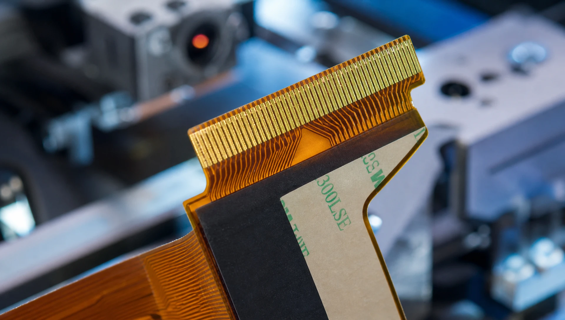
Observing specialized flex DFM guidelines prevents mechanical conductor fracture, copper tearing, and solder joint degradation in dynamic hardware installations.
Dynamic Bend Radius Calculation:
For Single-Sided Flex: Minimum Bend Radius = 6 * Overall Cable Thickness
For Double-Sided Flex: Minimum Bend Radius = 10 * Overall Cable Thickness
For Multi-Layer Flex: Minimum Bend Radius = 15 * Overall Cable Thickness
Formula: Minimum Bend Radius = K * Total Circuit Thickness (where K is the flex multiplier).
Staggered Trace Routing: Avoid stacking top and bottom traces directly over one another on double-sided flex circuits. Staggering traces reduces internal mechanical tension during bending (I-beam effect).
Teardrop Pad Fillets: Add teardrop fillets at all pad-to-trace transitions to eliminate localized stress concentration points and prevent copper conductor tearing during flexure.
Cross-Hatched Ground Planes: Replace solid copper ground planes with cross-hatched copper grids (e.g., 60% copper coverage) in flexible zones to retain flexibility and impedance control without stiffening the assembly.
High-reliability flex circuits used in medical devices, automotive control systems, and industrial equipment demand rigorous inline quality inspection and stress testing.
Dynamic Flex Testing (IPC-TM-650 2.4.3): Samples from production lots undergo automated endurance testing, flexing repeatedly around precision mandrels while monitoring circuit resistance in real time to verify conductor integrity.
3D Automated Optical Inspection (AOI): Inspects fine-pitch traces for etch defects, micro-burrs, pinholes, and alignment deviations prior to coverlay lamination.
Thermal Shock and Humidity Cycling: Verifies that adhesiveless polyimide laminates withstand rapid temperature transitions from -55°C to +125°C without delamination or barrel cracking in plated through-holes.
To evaluate our certified production equipment, IPC Class 3 quality controls, and volume processing specifications, visit our comprehensive
Industrial procurement directors frequently evaluate whether to maintain discrete wire harnessing or transition to custom fpc fabrication services. The comparative table below outlines key operational metrics.
| Performance Metric | Discrete Cable Harnessing | Custom Flexible Circuit (FPC) | Operational Advantage for Factory Clients |
| Spatial Footprint | Bulky, high volume requirement | Ultra-thin profile (< 0.20 mm) | Reclaims internal housing space for expanded battery capacity or additional features. |
| Total Weight | Heavy wire bundles and insulation | Ultra-lightweight polyimide film | Reduces total payload weight by up to 70% in aerospace, drone, and portable electronics. |
| Assembly Installation Error Rate | Higher risk of manual wiring misconnections | 100% Keyed / Foolproof Installation | Eliminates wiring mistakes, lowers rework costs, and accelerates assembly throughput. |
| Dynamic Bend Life | Subject to conductor strand fatigue | Over 1,000,000 continuous cycles | Guarantees long-term field reliability in moving robotic joints and hinge mechanisms. |
| SMT Component Integration | Requires separate terminal blocks | Direct SMT placement on FPC | Consolidates components onto a single unified assembly, reducing overall BOM count. |
Achieving reliable, high-yield flexible circuit production requires a dedicated manufacturing partner with specialized equipment and technical expertise. As a global leader in fpc fabrication services, ApolloPCB provides complete end-to-end solutions for factory clients worldwide.
Our modern manufacturing facilities feature high-precision LDI exposure lines, automated coverlay lamination presses, CO2/UV laser drilling machines, automated optical inspection systems, and dynamic flex endurance testing equipment. From quick-turn prototypes to high-volume production runs, ApolloPCB maintains strict IPC Class 2 and Class 3 compliance across every batch.
We provide comprehensive material selection guidance, custom stackup modeling, stiffener integration, and complimentary DFM/DFA engineering reviews to ensure your flexible circuits deliver flawless field performance.
Optimize your hardware designs, reduce total assembly weight, and accelerate time-to-market with confidence. Visit our
ApolloPCB supports high-density trace widths and spacing down to 0.05 mm (2 mils) using advanced Laser Direct Imaging (LDI) and vacuum-controlled chemical etching processes under strict IPC Class 3 guidelines.
ApolloPCB integrates FR-4 stiffeners for SMT component support, stainless steel stiffeners for maximum mechanical rigidity, polyimide stiffeners for ZIF connector specification matching, and 3M pressure-sensitive adhesives (PSA) for direct housing attachment.
Every production batch undergoes 100% electrical open/short flying probe testing, 3D AOI inspection, and IPC-TM-650 dynamic flex endurance testing. We verify that copper conductors and polyimide coverlays withstand continuous dynamic flexing without micro-cracking or impedance drift.

Got project ready to assembly? Contact us: info@apollopcb.com



 Whatsapp 0086 755 29438407
 Mail info@apollopcb.com
 Tel 0086 755 29438407


ABOUT US

PRODUCTS
TECHNOLOGY
KNOWLEDGE CENTRE
CULTURE
NEWS
We're not around but we still want to hear from you! Leave us a note:

Leave Message to APOLLOPCB
