-
- PCB TYPE
- PRINTED CIRCUIT BOARD PROTOTYPE ALUMINUM PRINTED CIRCUIT BOARD R&F PCB FPC HIGH FREQUENCY PCB HIGH-TG PCB HEAVY COPPER PCB HDI PCB PCB FOR LIGHTING METAL CORE PCB
time:Aug 20. 2025, 16:24:55
The 3mm Diameter Counterbore CEM3 PCB represents a critical intersection of precision engineering and practical functionality, offering a tailored solution for mounting components that require both stability and a low-profile design. A counterbore—distinct from a countersink—creates a flat-bottomed, cylindrical recess that allows the head of a fastener or the base of a component to sit entirely below the PCB surface, with the shank or lead extending through the hole. In CEM3 PCBs, which balance affordability with reliable mechanical performance, a 3mm diameter counterbore is particularly valuable: it accommodates common micro-fasteners (e.g., M2 screws) and small components (e.g., connectors, sensors) while leveraging CEM3’s unique structure to distribute stress evenly. This article examines the technical considerations, manufacturing processes, quality standards, and applications of 3mm diameter counterbores in CEM3 PCBs, highlighting their role in ensuring secure, space-efficient assemblies in modern electronics.
A 3mm diameter counterbore in a CEM3 PCB is more than a simple recess; it is a precision feature designed to address specific engineering challenges in component mounting:
The 3mm diameter is ideally suited for small fasteners commonly used in electronics, such as M2 screws, which have a 2mm shank diameter. The counterbore’s flat bottom ensures the screw head sits flush with or below the PCB surface, preventing protrusions that could snag on other components or the device housing. In CEM3 PCBs used in portable electronics—like handheld scanners—this secure retention prevents screws from loosening due to vibration, a common issue with non-recessed fasteners.
Modern electronics pack increasing functionality into smaller spaces, requiring high-density PCBs where even minor component movement can cause short circuits. A 3mm counterbore in a CEM3 PCB provides a stable platform for components like surface-mount connectors or sensors, ensuring they remain anchored during thermal cycling or physical stress. For example, in a CEM3-based IoT sensor node, a 3mm counterbore securing a Bluetooth module prevents the component from shifting and disrupting antenna alignment, maintaining reliable connectivity.
CEM3 PCBs used in compact devices are often thin (1.0–1.6mm), making them vulnerable to cracking under the pressure of tightened fasteners. A 3mm counterbore distributes the force of the fastener head across a larger area of the CEM3 material, reducing stress concentration in the epoxy matrix and glass fibers. This is critical in applications like wearable fitness trackers, where the PCB is repeatedly bent, and localized stress could lead to mechanical failure.
In devices with strict size constraints—such as medical monitors or automotive control modules—a 3mm counterbore allows components to occupy vertical space within the PCB rather than protruding outward. This reduces the overall device thickness by up to 20%, enabling sleeker designs without sacrificing functionality. In CEM3 PCBs, which are often chosen for their lightweight properties, this space efficiency is a key advantage over thicker, higher-cost substrates.

The 3mm diameter counterbore in CEM3 PCBs presents unique challenges due to the material’s structure and the precision required to achieve consistent recesses:
CEM3’s layered composition—non-woven glass core, woven glass outer layers, and epoxy resin—behaves differently under cutting tools than homogeneous materials. The non-woven core, with its porous, randomly oriented fibers, can compress or tear during counterboring, creating uneven bottom surfaces. The woven outer layers, by contrast, are denser and more resistant to cutting, potentially leading to raised edges or frayed fibers at the counterbore’s rim. These inconsistencies can prevent components from seating flush, compromising both mechanical stability and electrical performance.
A 3mm counterbore typically requires a depth of 0.5–0.8mm to accommodate standard fastener heads, a dimension that demands tight tolerances (±0.05mm). In CEM3 PCBs, variations in material thickness—common across production batches—can make consistent depth control difficult. A counterbore that is too shallow leaves the fastener head protruding, while one that is too deep weakens the PCB by removing excess material, increasing the risk of cracking around the hole.
The cutting process for 3mm counterbores generates friction, which can heat the CEM3 material to temperatures that soften the epoxy resin. This softened resin can flow into the counterbore, creating burrs or reducing the recess diameter. Additionally, glass fiber debris—too large to be easily evacuated by standard cooling systems—can accumulate in the counterbore, scratching the surface or interfering with component seating. In high-volume production, this debris buildup can also dull tools prematurely, leading to inconsistent recesses.
A 3mm counterbore must be perfectly concentric with the through-hole that extends through the PCB, ensuring the fastener shank or component lead aligns correctly. Misalignment—even by 0.1mm—can cause the fastener to bind or the component to sit at an angle, creating stress points in the CEM3 material. Achieving this alignment is challenging in CEM3 due to its slightly variable fiber density, which can cause tools to drift during cutting.
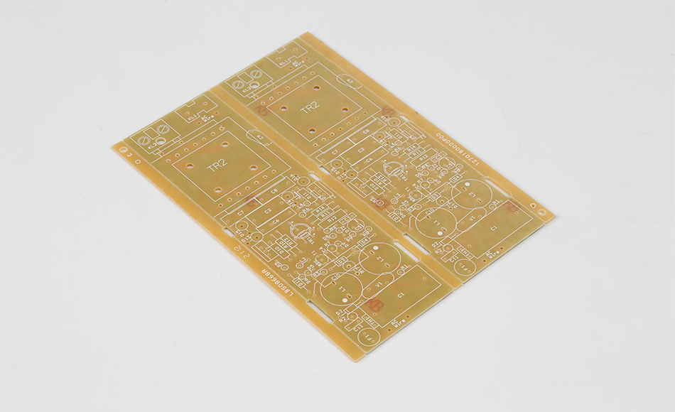
Producing reliable 3mm diameter counterbores in CEM3 PCBs requires specialized tooling, optimized processes, and careful attention to material properties:
Carbide End Mills with Flat Bottoms: These tools are designed to create precise, flat-bottomed recesses, essential for 3mm counterbores. Carbide’s hardness ensures it cuts through glass fibers cleanly, reducing fraying and maintaining consistent diameter.
TiAlN-Coated Tools: Titanium aluminum nitride coatings reduce friction between the tool and CEM3 material, lowering heat generation and extending tool life. This is particularly valuable in high-volume production, where tool changes can disrupt efficiency.
Two-Flute Design: Tools with two flutes enhance debris evacuation, preventing glass fiber buildup in the counterbore. The flutes are spaced to balance cutting efficiency with stability, reducing vibration that could cause uneven recesses.
Controlled Spindle Speeds: Operating at 20,000–30,000 RPM balances cutting speed with heat generation, ensuring the epoxy resin remains stable while the glass fibers are sheared cleanly.
Stepwise Depth Cutting: Instead of cutting the full counterbore depth in one pass, the tool makes multiple shallow passes (0.1–0.2mm each). This reduces pressure on the CEM3 material, minimizing tearing in the non-woven core and ensuring a flat bottom.
Coolant Delivery Systems: Directed mist coolant is applied directly to the cutting area to dissipate heat and flush away debris. The coolant is formulated to be compatible with CEM3’s epoxy resin, avoiding chemical reactions that could weaken the material.
Pre-Drilled Pilot Holes: A small pilot hole (typically 1.5–2mm diameter) is drilled first to guide the counterbore tool, ensuring concentricity with the final through-hole. This step is critical for preventing misalignment in CEM3, where fiber density variations can cause tool drift.
CNC Positioning with Vision Systems: Computer numerical control (CNC) machines equipped with optical sensors verify the PCB’s position before counterboring, adjusting for any slight shifts in the material. This ensures the 3mm counterbore is placed exactly where designed, even in high-volume production.
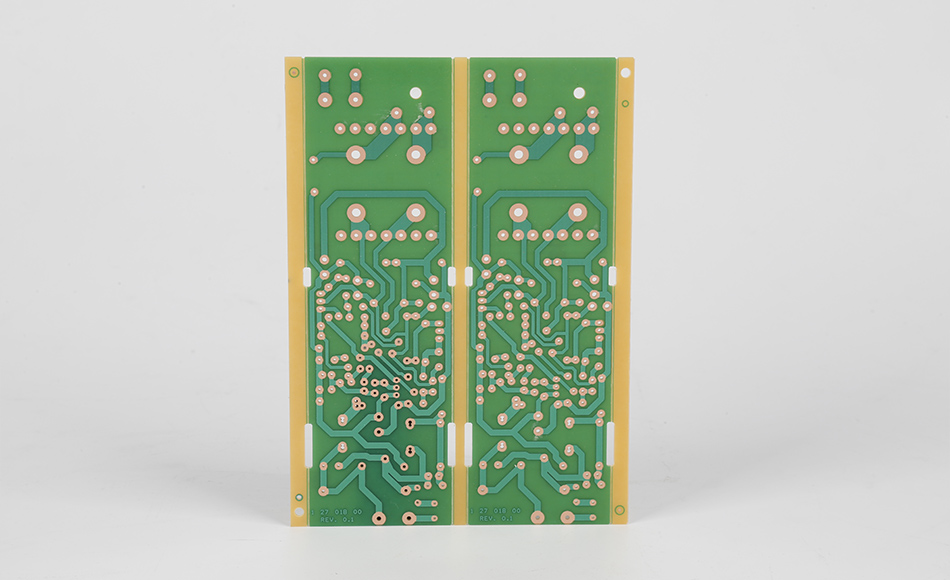
Ensuring the integrity of 3mm diameter counterbores in CEM3 PCBs requires rigorous inspection and testing to verify dimensional accuracy and material performance:
Optical Profilometry: This non-contact method uses laser scanning to measure the counterbore’s diameter, depth, and bottom flatness with micron-level precision. It can detect even minor deviations, such as a 0.03mm variation in diameter, which could affect fastener fit.
Coordinate Measuring Machines (CMMs): For critical applications, CMMs with touch probes physically map the counterbore’s geometry, verifying concentricity with the through-hole and ensuring the recess is perpendicular to the PCB surface.
Cross-Section Analysis: Microscopic examination of sliced CEM3 samples reveals whether the counterbore process caused delamination between layers or fiber damage. This is particularly important for assessing the risk of long-term mechanical failure.
Pull-Test Validation: Fasteners are inserted into counterbores and subjected to controlled pulling forces to measure retention strength. This test ensures the CEM3 material can withstand operational stresses without cracking or deforming around the counterbore.
Component Fit Validation: Actual components (e.g., M2 screws, micro-connectors) are installed in sample counterbores to verify flush seating and secure retention. This step identifies issues like burrs or uneven bottoms that may not appear in dimensional checks.
Environmental Cycling: Test PCBs undergo temperature cycles (-40°C to 85°C) and vibration testing to simulate real-world conditions. After cycling, counterbores are re-inspected for cracks or dimensional changes that could compromise performance.
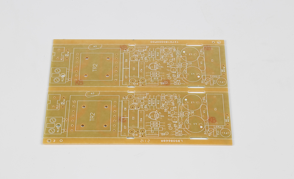
3mm diameter counterbores in CEM3 PCBs are integral to a range of devices where secure, low-profile component mounting is essential:
Smartphones and Tablets: Internal CEM3 PCBs use 3mm counterbores to secure battery connectors and display cables, ensuring these critical components remain stable during drops or impacts.
Wearable Devices: Fitness trackers and smartwatches leverage 3mm counterbores to mount sensors and charging pins, maintaining a slim profile that conforms to the user’s wrist.
Control Panels: CEM3 PCBs in factory control systems use 3mm counterbores to secure membrane switches and LED indicators, preventing loosening due to machinery vibrations.
Robotics: Small robotic arms and drones rely on 3mm counterbores in CEM3 PCBs to mount motors and position sensors, ensuring precise movement without excess weight.
Portable Diagnostics: Handheld blood glucose monitors and pulse oximeters use 3mm counterbores to secure test strip connectors and display modules, ensuring reliability in clinical settings.
Patient Monitors: CEM3 PCBs in bedside monitors employ 3mm counterbores to mount wiring harnesses, reducing the risk of disconnections during patient care.
In-Cabin Systems: Infotainment and climate control PCBs use 3mm counterbores to secure USB ports and control knobs, withstanding temperature fluctuations and vehicle vibrations.
Sensor Modules: Parking assist and lane departure sensors rely on 3mm counterbores in CEM3 PCBs to maintain alignment, ensuring accurate readings critical for driver safety.
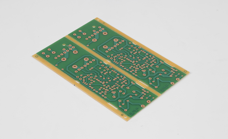
Designers and manufacturers can optimize 3mm diameter counterbores in CEM3 PCBs by following these guidelines:
Specify Clearance Zones: Maintain a 0.3mm gap between the counterbore and copper traces or solder masks to avoid damaging conductive paths during cutting.
Match Counterbore Depth to Fastener Heads: Ensure the counterbore depth (typically 0.5–0.8mm) matches the fastener head height, preventing protrusions or excessive material removal.
Avoid Placement Near PCB Edges: Position counterbores at least 1.5mm from the PCB edge to prevent weakening the substrate, especially in thin CEM3 PCBs.
Material Batch Testing: Test counterboring parameters on samples from each CEM3 batch, as fiber density and resin content can vary slightly and affect cutting performance.
Tooling Calibration: Regularly calibrate CNC machines and counterbore tools to ensure they maintain 3mm diameter precision, particularly after extended use.
Torque Testing: Verify that fasteners in 3mm counterbores can be tightened to the recommended torque (typically 0.5–1.0 Nm for M2 screws) without damaging the CEM3 material.
Long-Term Reliability Checks: Conduct accelerated aging tests on assembled PCBs to ensure counterbores remain stable over time, even under repeated thermal and mechanical stress.
Advancements in manufacturing are enhancing the precision and efficiency of 3mm diameter counterbores in CEM3 PCBs:
Fiber laser systems are being tested for creating 3mm counterbores, offering non-contact cutting that minimizes heat damage to CEM3’s epoxy resin. Lasers can achieve extremely consistent diameters and flat bottoms, reducing fiber fraying and improving component fit. While currently more expensive than mechanical methods, laser systems are becoming viable for high-precision applications like medical devices.
Machine learning algorithms analyze real-time data from cutting sensors to adjust speed, feed rate, and coolant flow for each CEM3 batch. By predicting how material variations affect counterbore quality, these systems ensure consistent results across production runs, reducing waste and improving yield.
Robotic systems with micro-brush attachments are being used to remove burrs from 3mm counterbores, ensuring a smooth surface for component mounting. These systems work in tandem with vision inspectors to verify deburring quality, maintaining precision while increasing throughput.
The 3mm Diameter Counterbore CEM3 PCB exemplifies how precision engineering can enhance the functionality of mid-range substrates, offering a secure, space-efficient solution for component mounting in modern electronics. By addressing the unique challenges of CEM3’s layered structure through specialized tooling, optimized processes, and rigorous quality control, manufacturers ensure these counterbores meet the demands of applications ranging from consumer devices to medical equipment. As electronics continue to shrink and demand greater reliability, 3mm diameter counterbores in CEM3 PCBs will remain a critical feature, enabling the secure integration of components in tight spaces without sacrificing performance or cost-effectiveness. For engineers and manufacturers, understanding the nuances of these precision recesses is key to creating assemblies that are both durable and efficient, driving innovation in the electronics industry.

Got project ready to assembly? Contact us: info@apollopcb.com


We're not around but we still want to hear from you! Leave us a note:

Leave Message to APOLLOPCB
