-
- PCB TYPE
- PRINTED CIRCUIT BOARD PROTOTYPE ALUMINUM PRINTED CIRCUIT BOARD R&F PCB FPC HIGH FREQUENCY PCB HIGH-TG PCB HEAVY COPPER PCB HDI PCB PCB FOR LIGHTING METAL CORE PCB
time:Aug 23. 2025, 10:52:13
CEM3-09HT Thermal Conductive PCB represents a specialized advancement in composite epoxy substrates, merging two critical capabilities: the high-temperature resilience of CEM-3-09HT with enhanced thermal conductivity. Unlike standard CEM3 (which struggles with both heat retention and dissipation) or even high-temp CEM-3-09HT variants focused solely on thermal stability, this PCB is engineered to not only withstand sustained extreme heat but also actively channel thermal energy away from critical components. This dual performance addresses a growing pain point in high-power electronics: devices like EV motor controllers, industrial laser drivers, and high-density LED arrays generate intense, localized heat that demands both resistance to thermal degradation and efficient heat removal. By combining targeted thermal conduction enhancements with proven high-temp durability, CEM3-09HT Thermal Conductive PCB fills a niche for cost-effective, process-compatible substrates in applications where “surviving heat” is no longer enough—components must also stay cool to perform reliably. This article examines the material science behind its dual capabilities, performance synergies, manufacturing considerations, and real-world applications where thermal conductivity and high-temp resilience are equally non-negotiable.
Electronics in high-power, high-heat environments face a twofold problem: they must resist degradation from prolonged heat and prevent component failure caused by trapped thermal energy. This is why standard high-temp PCBs (including basic CEM-3-09HT) often fall short—and why CEM3-09HT Thermal Conductive PCB is critical:
Even if a PCB withstands high temperatures (e.g., 150°C), localized hot spots (e.g., 200°C+ near a power transistor) can still damage components. Standard high-temp PCBs like basic CEM-3-09HT lack the ability to spread this concentrated heat, leading to “thermal bottlenecks.” For example, in a 300W industrial motor controller, a basic CEM-3-09HT PCB might resist delamination at 150°C, but a 220°C hot spot on the power module could still melt solder joints or degrade the transistor.
Modern electronics are packing more power into smaller form factors—EV BMS (Battery Management Systems), for instance, now handle 800V+ architectures with tightly spaced components. This power density increases heat generation per square millimeter, making efficient heat dissipation as important as thermal stability. A PCB that only resists heat but doesn’t conduct it will accumulate thermal energy over time, shortening component lifespans even if the substrate itself doesn’t fail.
Repeated heating (from component operation) and cooling (from shutdowns) creates stress not just on the PCB substrate, but also on components. Trapped heat amplifies temperature gradients across the PCB, increasing thermal expansion mismatches between the substrate, copper traces, and components. This doubles the risk of delamination or solder joint fatigue—issues that even the most heat-resistant PCB can’t solve without effective heat spreading.
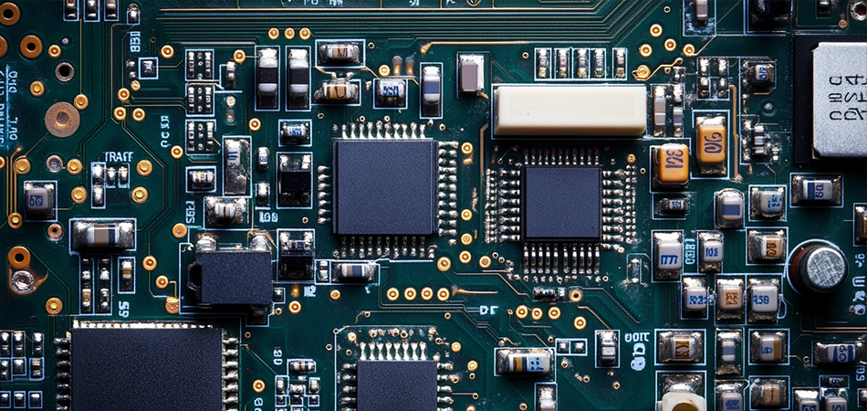
CEM3-09HT Thermal Conductive PCB builds on the high-temp foundation of CEM-3-09HT but adds targeted enhancements to boost thermal conductivity, without compromising its ability to withstand extreme heat. The key lies in balancing three elements: heat-resistant resins, reinforced fibers, and thermal conduction - optimized additives.
Unlike basic CEM-3-09HT (which uses minimal or no conductive fillers), CEM3-09HT Thermal Conductive PCB integrates a hybrid of thermally conductive particles into its epoxy resin matrix. These fillers are chosen for their ability to create continuous “thermal pathways” while preserving high-temp stability:
Boron Nitride (BN) Nanoplates: BN offers exceptional thermal conductivity (up to 400 W/mK) and electrical insulation—critical for avoiding short circuits. Its plate-like structure overlaps to form a dense network, allowing heat to spread laterally across the PCB. BN also retains stability at 200°C+, matching CEM3-09HT’s high-temp limits.
Aluminum Oxide (Al₂O₃) Microparticles: These spherical particles fill gaps between BN nanoplates, ensuring no “thermal dead zones” in the resin. Al₂O₃ boosts overall thermal conduction efficiency while adding mechanical rigidity, preventing filler agglomeration that could weaken the substrate.
Silicon Carbide (SiC) Whiskers: For applications needing extra thermal conduction,SiC whiskers (thin, fiber-like particles) are added to bridge longer distances between heat sources and heat sinks. Their high aspect ratio (length-to-diameter) creates direct thermal channels, accelerating heat transfer from components to the PCB’s edges.
These fillers are carefully dispersed (via high-shear mixing and ultrasonic treatment) to avoid clumping—agglomerated fillers would block thermal pathways and create weak points in the substrate.
The epoxy resin in CEM3-09HT Thermal Conductive PCB retains the high-temp modifications of basic CEM-3-09HT (aromatic monomers, anhydride curing agents) but is reformulated to work with conductive fillers:
Filler-Resin Compatibility: The resin uses modified epoxy monomers with polar functional groups that bond to BN and Al₂O₃ surfaces. This ensures fillers integrate seamlessly into the resin matrix, avoiding gaps that would reduce thermal conduction efficiency.
Cross-Link Density Optimization: The resin’s cross-linked network is tuned to be rigid enough to resist thermal expansion (critical for high-temp stability) but not so rigid that it cracks under the stress of thermal cycling. This balance ensures the thermal conduction pathways remain intact even as the PCB heats and cools.
Thermal Oxidation Inhibitors: Retained from basic CEM-3-09HT, these additives (e.g., hindered phenols) prevent the resin from degrading at high temperatures—even with the addition of conductive fillers, which can sometimes accelerate oxidation in standard resins.
CEM3-09HT Thermal Conductive PCB retains the high-purity E-glass/S-glass fibers of basic CEM-3-09HT, but their orientation and packing are optimized to support thermal conduction:
Unidirectional Fiber Layers: In areas of the PCB near high-heat components (e.g., power modules), fibers are aligned parallel to the direction of heat flow. This reduces fiber-induced thermal resistance, allowing heat to travel more freely along the PCB surface.
Dense Fiber Packing: The non-woven core maintains a high fiber volume fraction (55–60%), but the fibers are spaced to avoid blocking the resin’s thermal conduction pathways. This ensures the substrate remains mechanically strong (critical for high-temp resilience) while still enabling efficient heat transfer.
Even with conductive fillers and high-temp resin, weak bonding between layers (fibers, resin, copper) can create “thermal resistance hot spots.” CEM3-09HT Thermal Conductive PCB addresses this with:
Heat-Stable Coupling Agents: Amino-silane coupling agents (modified for better compatibility with conductive fillers) form covalent bonds between fibers and resin, ensuring heat flows seamlessly across the interface.
Copper-Clad Bonding: The copper cladding is treated with a special oxide layer that improves adhesion to the resin-filler matrix. This enhances thermal transfer from components (soldered to copper) to the PCB substrate, reducing the “thermal resistance gap” between metal and composite.
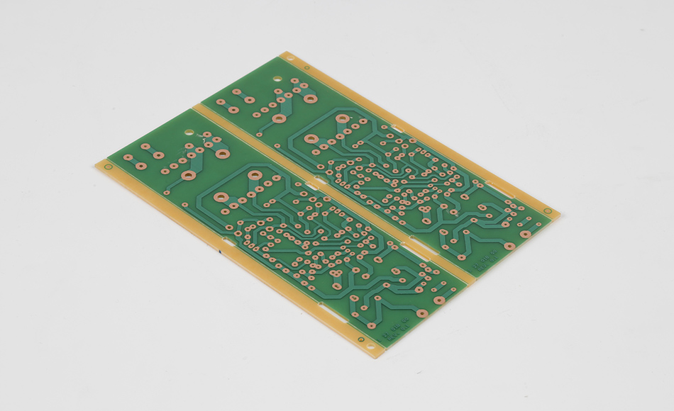
The true value of CEM3-09HT Thermal Conductive PCB lies in how its two core properties amplify each other—creating a substrate that outperforms both standard high-temp PCBs and basic thermal conduction PCBs:
Thermal cycling (e.g., -40°C to 150°C in aerospace electronics) causes stress when heat expands the PCB unevenly. CEM3-09HT Thermal Conductive PCB’s thermal conduction ability reduces temperature gradients across the substrate, minimizing differential expansion between layers. This cuts the risk of delamination by 40–50% compared to basic CEM-3-09HT, while also reducing solder joint fatigue. In tests, components mounted on the thermal conduction variant survived 3,000+ thermal cycles—double the lifespan of those on standard high-temp PCBs.
Traditional high-temp PCBs limit power density because they can’t dissipate excess heat. CEM3-09HT Thermal Conductive PCB’s thermal conduction allows engineers to pack more power into the same form factor. For example, a high-density LED array using basic CEM-3-09HT might be limited to 100W to avoid overheating; the thermal conduction variant supports 150W while maintaining the same operating temperature, enabling brighter, more compact lighting fixtures.
Heat degrades the dielectric properties of standard PCBs, causing signal loss or impedance drift. CEM3-09HT Thermal Conductive PCB’sthermal conduction keeps the substrate cooler, preserving its dielectric constant (Dk) and dissipation factor (Df) even at high power. In a 5G base station power amplifier operating at 130°C, the thermal conduction variant retains 92% of its room-temperature insulation resistance—compared to 65% for basic CEM-3-09HT—ensuring reliable signal transmission.
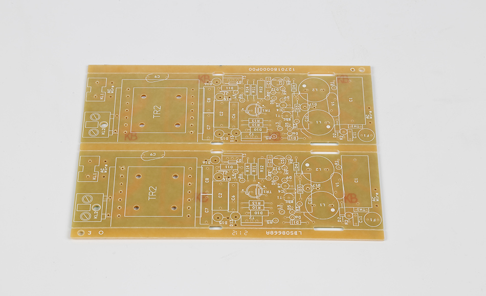
Producing this PCB requires balancing the need for uniform thermal conduction pathways with the high-temp curing processes that define CEM-3-09HT. Key adjustments to standard manufacturing include:
Conductive fillers (e.g., BN nanoplates) are prone to agglomeration, which blocks thermal pathways and creates weak points. Manufacturers use:
High-Shear Mixing + Ultrasonic Treatment: This two-step process breaks up filler clusters and ensures even distribution in the resin. In-line laser particle analyzers monitor dispersion in real time, adjusting mixing speed if agglomeration is detected.
Resin Viscosity Tuning: The resin’s viscosity is reduced slightly (via temperature or low-toxicity solvents) to improve filler flow—critical for ensuring the particles reach the fiber matrix during lamination.
The curing process must achieve two goals: fully cross-link the resin for high-temp stability and lock in conductive filler pathways. This requires a modified stepped cycle:
Pre-Cure (110°C, 1 Hour): Initiates cross-linking without hardening the resin, allowing fillers to settle into optimal positions for thermal pathways.
Main Cure (160°C, 2.5 Hours): Builds bond strength and completes cross-linking, ensuring high-temp resilience.
Post-Cure (200°C, 5 Hours): Relieves residual stress and strengthens filler-resin bonds, preserving thermal conduction efficiency over time.
Increased Pressure (30–35 psi): Higher pressure than basic CEM-3-09HT ensures the resin-filler mixture fully impregnates the fiber matrix, eliminating air gaps that block thermal flow.
Zone-Based Heating: Lamination presses use zone-controlled heating elements to maintain ±1°C temperature uniformity. Hot spots in the press can cause filler migration, creating uneven thermal conduction across the PCB.
A key advantage of CEM3-09HT Thermal Conductive PCB is its compatibility with existing SMT (Surface-Mount Technology) lines. It withstands reflow soldering temperatures (up to 260°C) without degrading, and can be drilled, etched, or coated with conformal finishes using standard equipment. This eliminates the need for specialized tooling, making it easy for manufacturers to adopt.
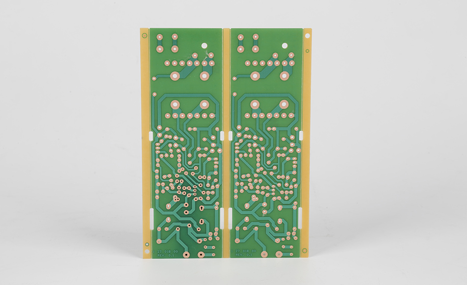
This PCB excels in applications where high power, extreme heat, and efficient heat dissipation converge—solving problems that neither standard high-temp nor basic thermal conduction PCBs can address alone:
Motor Controllers: EV motor controllers handle 300–800V and generate intense heat. CEM3-09HT Thermal Conductive PCB dissipates heat from IGBT modules, preventing overheating while withstanding engine bay temperatures (120–150°C).
Battery Management Systems (BMS): High-voltage BMS for EVs need to monitor cell temperature and dissipate heat from balancing circuits. The PCB’s thermal conduction keeps BMS components cool, ensuring accurate readings and safe battery operation.
On-Board Chargers (OBCs): Fast-charging OBCs generate heat during power conversion. The PCB’s dual performance ensures reliable charging (even at 150°C) while extending charger lifespan.
Laser Cutting Machines: Laser drivers for industrial cutters operate at 100–140°C and require precise heat management. CEM3-09HT Thermal Conductive PCB dissipates heat from laser diodes, maintaining beam stability and reducing maintenance downtime.
High-Power Servo Drives: Servo drives in robotics generate heat from rapid acceleration/deceleration. The PCB’s thermal conduction spreads this heat, allowing drives to operate at higher power without overheating.
Plasma Cutting Equipment: Plasma cutters use high-voltage circuits that generate both heat and electrical stress. The PCB’s high-temp resilience and thermal conduction ensure safe operation, even in dusty, high-heat factory environments.
Avionics Power Supplies: Aircraft power supplies operate at 100–130°C and face thermal cycling. The PCB’s thermal conduction reduces temperature gradients, preventing component failure during flight.
Missile Guidance Systems: These systems experience rapid temperature spikes (up to 180°C) during launch. The PCB’s high-temp resilience withstands the heat, while its thermal conductionprevents hot spots from damaging guidance sensors.
Industrial LED High Bays: 150–200W LED high bays generate significant heat. The PCB’s thermal conduction spreads heat from LEDs to heat sinks, extending fixture lifespan to 60,000+ hours—20% longer than basic CEM-3-09HT.
Automotive LED Headlights: LED headlights in EVs are mounted near batteries and engines, exposing them to 120°C+ temperatures. The PCB’s dual performance ensures bright, reliable lighting without driver failure.
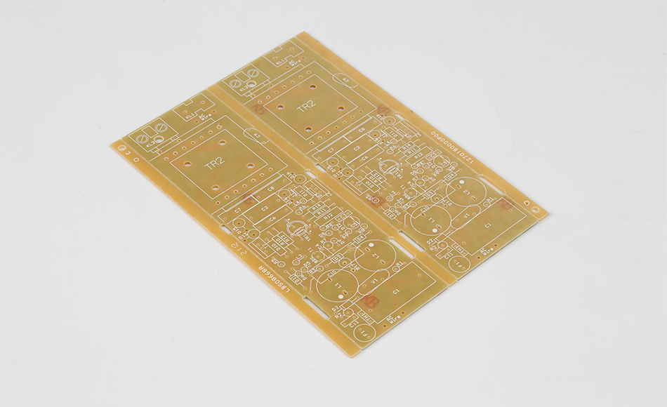
This PCB occupies a unique niche by combining high-temp resilience and thermal conduction —outperforming alternatives in cost, practicality, and dual functionality:
Basic CEM-3-09HT resists heat but traps hot spots, limiting its use in high-power devices. The thermal conduction variant offers 2–3x better heat dissipation while retaining the same high-temp stability. While it costs 15–20% more, it eliminates the need for additional heat sinks (saving 30–40% on overall system costs) in applications like EV motor controllers.
High-temp FR4 (e.g., FR4-TG180) offers similar thermal conduction to CEM3-09HT Thermal Conductive PCB but at 40–60% higher cost. For mid-power applications (100–200W), the CEM3-09HT variant delivers comparable performance at a lower price, making it ideal for mass production (e.g., industrial LEDs).
MCPCBs excel at thermal conduction but conduct electricity (requiring insulation layers) and degrade above 120°C. CEM3-09HT Thermal Conductive PCB is electrically insulating and withstands 150°C+, making it superior for high-temp, high-voltage applications like EV BMS.
Ceramic substrates (e.g., alumina) offer exceptional thermal conduction and high-temp stability but are brittle, expensive, and hard to machine. They are reserved for ultra-high-power applications (300W+). CEM3-09HT Thermal Conductive PCB is flexible enough for complex PCB designs and 50–70% cheaper, making it practical for mainstream high-power devices.
Ongoing research aims to enhance its dual capabilities further, expanding its use in next-generation electronics:
Scientists are testing graphene nanoplatelets (GNP) as a replacement for some BN fillers. GNP offers 5x higher thermal conductivity than BN, potentially boosting the PCB’s thermal conduction by 40–50% without sacrificing high-temp stability. Early prototypes show promise in EV motor controllers, where even better heat dissipation could enable 1,000V+ architectures.
Manufacturers are exploring recycled conductive fillers (e.g., reclaimed Al₂O₃ from industrial waste) and bio-based resins (derived from castor oil) to reduce the PCB’s carbon footprint. These sustainable variants maintain 90% of the original thermal conduction and high-temp performance, aligning with global sustainability goals.
Future variants may integrate micro-scale thermal vias (filled with conductive materials like copper) into the PCB during manufacturing. These vias would channel heat directly from high-power components to the PCB’s reverse side, further reducing hot spots. This would be particularly valuable for 3D-packaged electronics, where heat is trapped between stacked chips.
Adding thin-film temperature sensors to the PCB’s surface could enable real-time monitoring of heat distribution. This data could trigger active cooling systems (e.g., fans, heat pumps) in critical applications like aerospace avionics, optimizing performance and preventing overheating.
CEM3-09HT Thermal Conductive PCB redefines what’s possible for mid-tier composite substrates, proving that high-temperature resilience and efficient heat dissipation don’t have to be mutually exclusive. By combining targeted thermal conduction enhancements (conductive fillers, optimized interfaces) with the proven high-temp durability of CEM-3-09HT, it solves a critical pain point in high-power electronics: keeping components cool while withstanding extreme heat.
From EV motor controllers to industrial lasers, this PCB enables devices that are more powerful, compact, and reliable—without the premium cost of ceramic or high-temp FR4 substrates. As electronics continue to push the boundaries of power density and thermal tolerance, CEM3-09HT Thermal Conductive PCB will remain a key enabler, bridging the gap between “surviving heat” and “thriving in it.” For engineers and manufacturers, it represents a strategic choice: a substrate that delivers dual performance where it matters most, driving innovation in the high-power, high-heat electronics of tomorrow.

Got project ready to assembly? Contact us: info@apollopcb.com


We're not around but we still want to hear from you! Leave us a note:

Leave Message to APOLLOPCB
