-
- PCB TYPE
- PRINTED CIRCUIT BOARD PROTOTYPE ALUMINUM PRINTED CIRCUIT BOARD R&F PCB FPC HIGH FREQUENCY PCB HIGH-TG PCB HEAVY COPPER PCB HDI PCB PCB FOR LIGHTING METAL CORE PCB
time:Jun 27. 2025, 08:22:29
In the realm of electronic manufacturing, Aluminum Printed Circuit Boards (PCBs) have gained prominence for their exceptional thermal conductivity and mechanical robustness. Among the critical features that enhance their functionality, counterbore holes stand out as a fundamental design element. A counterbore hole in an aluminum PCB is a recessed hole with a larger diameter at the top, designed to accommodate the head of a flat - head screw or rivet, ensuring a flush surface finish. This article explores the technical aspects, design principles, manufacturing processes, and industry applications of counterbore holes in aluminum PCBs, highlighting their role in optimizing mechanical integrity and design efficiency.
Technical Fundamentals of Counterbore Holes
Definition and Core Functions
A counterbore hole in an aluminum PCB consists of two sections: a primary hole for the screw shaft and a larger - diameter upper recess (the counterbore) that allows the screw head to sit flush with the board's surface. This design serves three key purposes:
Mechanical Stability: Distributes clamping forces evenly across the board, reducing stress concentrations that could cause cracks.
Space Optimization: Minimizes protrusion, making it ideal for applications with limited vertical space.
Aesthetic Finish: Provides a smooth surface, crucial for products where the PCB is visible or requires a clean assembly.
Unlike tapped counterbore holes, standard counterbores do not include internal threading in the lower hole, relying on external nuts or pre - threaded components for fixation. This simplifies manufacturing while maintaining secure mechanical connections in non - load - bearing applications.
Design Differentiation from Tapped Counterbores
The primary distinction between counterbore and tapped counterbore holes lies in the absence of internal threading. Counterbores focus solely on accommodating the screw head, while tapped counterbores integrate threading for direct screw engagement. This makes counterbores suitable for applications where:
Threaded inserts or external fasteners are preferred.
Electrical conductivity through the screw is not required.
Simplified manufacturing with reduced threading steps is prioritized.
The depth and diameter of the counterbore are calculated based on the screw head dimensions, ensuring a precise fit without penetrating critical PCB layers.
Material Considerations for Aluminum PCBs
Aluminum's malleability presents both advantages and challenges for counterbore holes:
Advantages: Aluminum's ductility allows for clean counterbore edges with proper tooling.
Challenges: Soft aluminum may deform under excessive torque, necessitating:
Use of hardened washers to distribute pressure.
Surface treatments like anodizing to enhance wear resistance.
Avoidance of over - tightening during assembly.
For high - stress applications, manufacturers may reinforce counterbore holes with non - threaded inserts (e.g., brass or plastic) to prevent wall thinning or cracking.
Design Principles for Counterbore Holes
Mechanical Design Considerations
Hole Dimensions and Clearance
The counterbore diameter should be slightly larger than the screw head diameter to ensure free movement during assembly. Industry standards (e.g., ISO or ASME) guide typical clearances, but design factors include:
Screw head shape (flat, oval, or truss head).
Board thickness and aluminum alloy hardness.
Expected mechanical load on the connection.
The depth of the counterbore must fully recess the screw head while leaving sufficient material below the hole to maintain board strength.
Stress Distribution and Component Placement
Counterbore holes should be positioned away from:
PCB edges, where stress concentrations are higher.
High - density component areas to avoid thermal or mechanical interference.
Critical electrical traces, maintaining safe clearance (e.g., 0.5mm minimum from traces).
Finite Element Analysis (FEA) can simulate stress around counterbore holes in high - load applications, ensuring the design withstands dynamic forces like vibration or impact.
Electrical Design Considerations
Insulation and Clearance
Since counterbore holes do not typically serve as electrical paths, focus is on preventing short - circuits:
Maintain adequate distance from power/ground planes.
Use non - conductive washers if the screw might contact traces.
In EMI - sensitive designs, ensure counterbores do not disrupt shielding layers.
3.2.2 Thermal Management Impact
Counterbore holes themselves do not directly affect thermal performance, but their placement can influence heat dissipation:
Avoid blocking thermal vias or heat sink mounting areas.
Ensure counterbore - mounted components (e.g., heat sinks) have direct contact with the aluminum substrate for optimal heat transfer.
Manufacturing Processes for Counterbore Holes
Drilling and Counterboring Steps
Precision Drilling
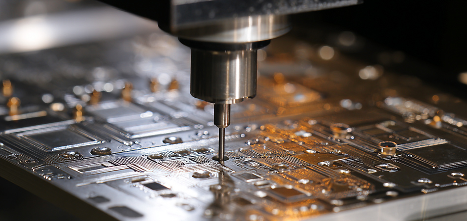
The process starts with drilling the primary hole using high - speed CNC machines. Key considerations:
Carbide - tipped drills for aluminum to minimize burrs.
Coolant application to prevent overheating and tool wear.
Drill speed and feed rate optimized for aluminum's thermal properties.
Counterboring Operation
A counterbore tool (conical or flat - bottomed) is used to create the upper recess:
Conical counterbores are ideal for flat - head screws, while flat - bottomed counterbores suit socket - head cap screws.
Spindle speed is reduced during counterboring to ensure a smooth surface finish.
Automated systems with vision alignment ensure concentricity between the primary hole and counterbore.
Deburring and Surface Treatment
Deburring Techniques
Post - machining, burrs around the counterbore are removed using:
Mechanical deburring (brushes or rotary tools).
Chemical deburring for delicate boards.
Plasma etching for micro - burr removal in high - precision applications.
Surface Finishing
To enhance durability and corrosion resistance:
Anodizing: Increases surface hardness and provides a protective oxide layer.
Electroless Nickel Immersion Gold (ENIG): Improves solderability if the counterbore interacts with conductive components.
Passivation: Reduces oxidation in aluminum, especially for outdoor applications.
Quality Control and Testing
Dimensional Inspection
Key measurements include:
Counterbore diameter and depth using optical comparators.
Concentricity between the primary hole and counterbore with CMMs.
Surface roughness assessment to ensure smooth edges (e.g., Ra ≤ 1.6μm for most applications).
Mechanical Integrity Testing
Torque Testing
Simulates assembly forces to:
Verify the board can withstand standard tightening torques without deformation.
Check for material fatigue in cyclic loading tests (e.g., vibration testing).
Visual and X - Ray Inspection
Visual: Checks for burrs, cracks, or uneven counterbore edges.
X - Ray: Ensures the counterbore does not penetrate internal layers in multi - layer PCBs.
Industry Applications of Counterbore Holes
Aerospace and Defense
In avionics and military systems, counterbore holes are used for:
Mounting lightweight components in aircraft, where flush surfaces reduce drag.
Securing heat sinks to aluminum PCBs in high - temperature environments.
Attaching EMI - shielding covers with non - conductive fasteners to prevent short - circuits.
Automotive Electronics
In vehicle electronics, counterbore holes enable:
Flush mounting of components in dashboard panels, reducing snag hazards.
Secure fixation of sensors in engine compartments, resistant to vibration.
Integration of heat - dissipating components without compromising thermal paths.
Medical Devices
In medical equipment, counterbore holes are valued for:
Sterilizable designs in surgical tools, where smooth surfaces prevent debris accumulation.
Precise component mounting in diagnostic devices, ensuring repeatable assembly.
Non - conductive fasteners in MRI - compatible equipment to avoid interference.
Consumer Electronics
In consumer products, counterbore holes facilitate:
Slim - profile designs in laptops and tablets by recessing screws.
Aesthetically pleasing assemblies where the PCB is visible (e.g., modular electronics).
Easy disassembly for repair, using standard fasteners with counterbore holes.
Future Trends and Challenges
Miniaturization and Micro - Counterbores
As electronics shrink, micro - counterbore holes (sub - 1mm diameter) require:
Ultrasonic machining for precise micro - recesses.
Laser - based counterboring for nano - scale surface finishes.
Composite Materials Integration
Aluminum - composite PCBs (e.g., aluminum core with polyimide dielectrics) demand:
Hybrid machining techniques to balance aluminum and composite material properties.
Adhesive - based fasteners for composite layers incompatible with traditional counterbores.
Sustainable Manufacturing
Eco - friendly practices include:
Water - based coolants in drilling/counterboring.
Recyclable aluminum alloys and lead - free surface treatments.
Minimal waste designs through precise CNC programming.
Automated Quality Assurance
AI - powered inspection systems:
Use machine vision to detect micro - burrs or dimensional variations.
Implement predictive maintenance for counterboring tools based on defect patterns.
Conclusion
Counterbore holes in aluminum PCBs are essential for achieving secure mechanical connections, optimizing space, and enhancing design aesthetics. As electronics evolve toward smaller, more robust designs, the precision and innovation behind counterbore technology will remain critical. By addressing challenges in miniaturization, material compatibility, and sustainability, manufacturers can unlock new applications in aerospace, automotive, medical, and consumer electronics— ensuring counterbore holes continue to be a cornerstone of efficient PCB design.

Got project ready to assembly? Contact us: info@apollopcb.com


We're not around but we still want to hear from you! Leave us a note:

Leave Message to APOLLOPCB
