-
- PCB TYPE
- PRINTED CIRCUIT BOARD PROTOTYPE ALUMINUM PRINTED CIRCUIT BOARD R&F PCB FPC HIGH FREQUENCY PCB HIGH-TG PCB HEAVY COPPER PCB HDI PCB PCB FOR LIGHTING METAL CORE PCB
time:Aug 19. 2025, 20:05:47
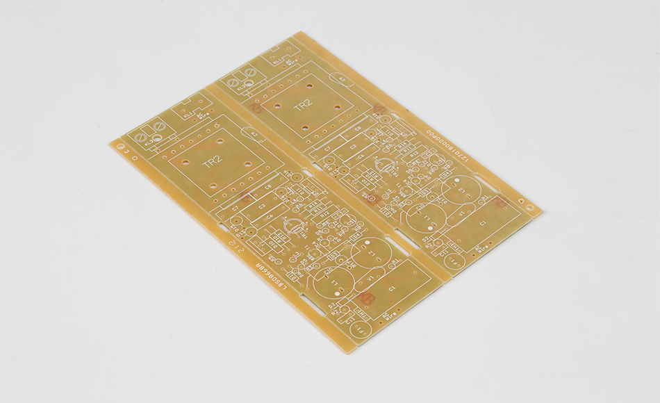
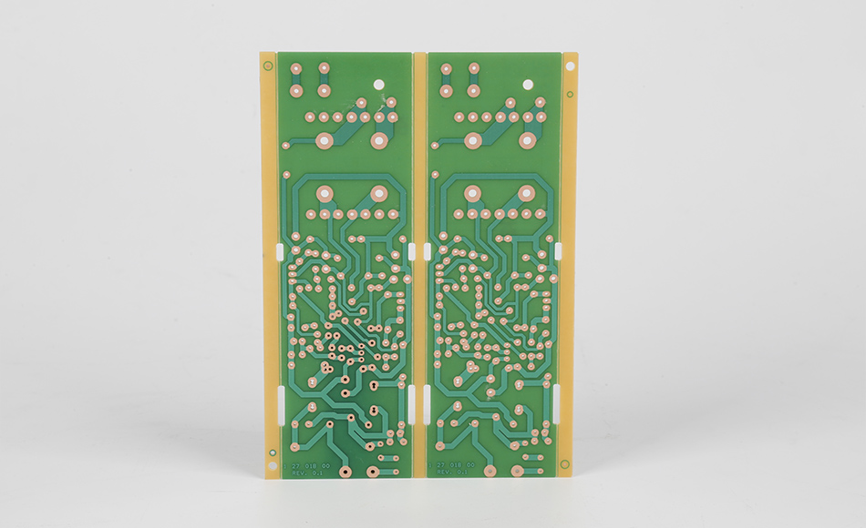
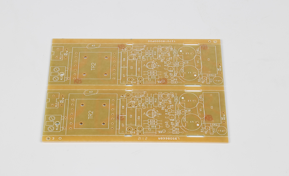
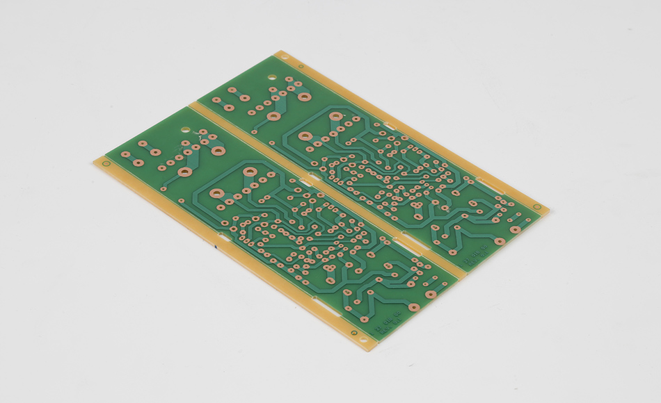
Countersink Holes in CEM3 PCB are a fundamental yet often underappreciated feature that bridges the gap between PCB manufacturing and device assembly. These conical recesses, designed to accommodate fasteners, connectors, or component leads, ensure that hardware sits flush with the PCB surface, preventing protrusions that could compromise functionality, durability, or safety. In CEM3 PCBs—known for their balanced blend of affordability, mechanical stability, and electrical performance—countersink holes play a critical role in applications ranging from consumer electronics to industrial equipment. Unlike other substrates, CEM3’s unique composition (non-woven glass core, woven glass layers, and epoxy resin) demands specialized approaches to countersinking to avoid delamination, fiber fraying, or uneven recesses. This article explores the design principles, manufacturing techniques, quality standards, and practical applications of countersink holes in CEM3 PCBs, highlighting their importance in creating reliable, well-assembled electronic devices.
Countersink holes in CEM3 PCBs serve multiple purposes that extend beyond simple aesthetics, directly impacting device performance and longevity:
When fasteners or components are mounted on a PCB, uneven pressure can create stress concentrations that weaken the substrate over time. Countersink holes distribute this pressure evenly across the CEM3 material, preventing cracks in the epoxy matrix or glass fibers. This is particularly important in CEM3 PCBs used in vibrating environments—such as industrial machinery or automotive applications—where repeated stress could otherwise lead to mechanical failure. For example, a countersink hole securing a motor mount in a CEM3-based pump controller ensures that vibrations are absorbed uniformly, extending the PCB’s lifespan.
Many electronic components, from connectors to sensors, require precise positioning to function correctly. Countersink holes act as alignment guides during assembly, ensuring that these components are centered and seated at the correct angle. In CEM3 PCBs with high component density—such as those in home automation controllers—this alignment prevents short circuits or signal loss caused by misaligned parts. A well-executed countersink ensures that a surface-mount connector, for instance, aligns perfectly with its mating part, maintaining consistent electrical contact.
In devices where size matters—such as portable electronics or compact industrial enclosures—countersink holes allow components to lie flush with the PCB surface, reducing the overall profile. This is especially valuable in CEM3 PCBs, which are often chosen for their lightweight properties in slim designs. A countersink hole in a CEM3-based tablet PCB, for example, allows the battery connector to sit flat, enabling a thinner device chassis without sacrificing structural support.
Flush-mounted components, enabled by countersink holes, minimize gaps where dust, moisture, or debris can accumulate. In CEM3 PCBs used in harsh environments—such as outdoor sensors or kitchen appliances—this reduces the risk of corrosion, short circuits, or insulation breakdown. The countersink’s conical shape also helps channel liquids away from sensitive components, adding an extra layer of protection.

CEM3’s unique composition presents specific challenges when creating countersink holes, requiring a nuanced understanding of how the material interacts with cutting tools:
CEM3’s construction—non-woven glass core sandwiched between woven glass layers—creates variations in density and hardness. The non-woven core, with its porous, randomly oriented fibers, is more susceptible to tearing or collapsing during countersinking, while the woven outer layers, with their tightly packed fibers, resist cutting and may fray if not handled properly. This contrast can lead to uneven countersink walls or “stepped” recesses, where the core material is removed faster than the outer layers. Such irregularities can prevent components from seating flush, undermining the hole’s purpose.
The epoxy resin that binds CEM3’s glass fibers is sensitive to heat and friction. During countersinking, excessive heat can soften the resin, causing it to flow into the recess and create burrs or blockages. This is particularly problematic in high-speed cutting, where friction generates significant thermal energy. Additionally, resin adhesion to glass fibers varies across CEM3 batches, affecting how cleanly the material separates during countersinking—weak adhesion can lead to fiber pull-out, leaving rough surfaces that interfere with component fit.
Countersink holes in CEM3 PCBs must be tailored to the hardware they accommodate. For example, a countersink designed for a flat-head screw requires a specific angle (typically 82° or 90°) to match the screw’s taper, ensuring full contact with the PCB surface. Mismatched angles can result in loose fasteners or cracked CEM3 material, as pressure is concentrated on uneven contact points. Similarly, countersinks for component leads must align with the lead’s diameter and insertion depth to avoid damaging the PCB or the component during assembly.

Producing high-quality countersink holes in CEM3 requires a combination of specialized tooling, optimized processes, and material-specific adjustments:
Carbide-Tipped Countersinks: Carbide tools offer superior hardness and wear resistance, making them ideal for cutting through CEM3’s glass fibers. Their sharp edges minimize fraying and maintain consistent hole geometry, even after extended use.
Variable Flute Designs: Tools with variable flute spacing reduce vibration during cutting, preventing uneven recesses caused by tool chatter. This is particularly useful for CEM3, where fiber density variations can amplify vibration.
Angle-Specific Cutters: Countersinks with pre-set angles (e.g., 82°, 90°, 120°) ensure compatibility with standard fasteners, reducing the risk of mismatched hardware and PCB.
Controlled Speed and Feed Rates: Moderate spindle speeds (15,000–30,000 RPM) balance cutting efficiency with heat generation, preventing resin softening. Slow, steady feed rates allow the tool to shear fibers cleanly, reducing fraying and burr formation.
Coolant Application: Mist coolant systems deliver a fine spray of lubricant to the cutting area, reducing friction and heat. For CEM3, water-based coolants are preferred, as they avoid chemical reactions with the epoxy resin that could weaken the material.
Sequential Drilling and Countersinking: Drilling the pilot hole first, then countersinking, ensures alignment and reduces tool slippage. This two-step process prevents off-center countersinks, which are common in CEM3 due to its uneven fiber density.
Deburring: After countersinking, mechanical brushes or ultrasonic cleaning remove loose glass fibers and resin burrs from the hole edges. This step is critical for CEM3, as frayed fibers can interfere with component seating or cause electrical shorts.
Surface Treatment: Applying a thin layer of conformal coating to countersink holes seals exposed glass fibers, preventing moisture absorption and improving long-term durability. This is especially valuable in humid environments, where unprotected CEM3 is prone to degradation.

Ensuring consistent countersink quality in CEM3 PCBs requires rigorous inspection and testing, focusing on both dimensional accuracy and material integrity:
Optical Inspection Systems: High-resolution cameras measure countersink diameter, depth, and angle, comparing them to design specifications. These systems can detect deviations as small as 0.01mm, ensuring compliance with tight tolerances.
Coordinate Measuring Machines (CMMs): For critical applications, CMMs use touch probes to map the countersink’s geometry, verifying concentricity with the pilot hole and ensuring uniform wall angles.
Microscopic Analysis: Examining countersink cross-sections under a microscope reveals fiber damage, delamination, or resin flow issues. This helps identify problems like uneven cutting or excessive heat during manufacturing.
Pull-Test Validation: Inserting fasteners into countersink holes and measuring the force required to loosen them ensures that the CEM3 material can withstand operational stresses without cracking or deforming.
Component Fit Testing: Mock assembly with actual hardware verifies that components seat flush and securely in the countersink holes. This step catches issues like mismatched angles or excessive burrs that may not appear in dimensional checks.
Environmental Cycling: Exposing CEM3 PCBs to temperature and humidity cycles (-40°C to 85°C, 85% RH) tests the countersink holes’ resilience. After cycling, holes are re-inspected for cracks, delamination, or dimensional changes that could affect performance.

Countersink holes in CEM3 PCBs are integral to a wide range of devices, each leveraging their benefits for specific needs:
Home Appliances: Refrigerator control boards use countersink holes to secure wiring harness connectors, ensuring a low-profile design that fits within tight appliance enclosures.
Audio Equipment: Speaker crossover PCBs rely on countersink holes to mount capacitors and inductors flush, reducing vibration-induced noise and improving sound quality.
Control Panels: CEM3 PCBs in factory control systems use countersink holes to secure membrane switches, ensuring the switches make consistent contact with the PCB’s conductive traces.
Sensor Enclosures: Environmental sensor PCBs use countersink holes to attach protective covers, creating a sealed barrier against dust and moisture while maintaining a compact design.
In-Cabin Systems: Infotainment and climate control PCBs use countersink holes to mount connectors, withstanding vehicle vibrations that could loosen non-recessed hardware.
Lighting Modules: LED driver PCBs in automotive lighting use countersink holes to secure heat sinks, ensuring maximum contact area for efficient thermal transfer.
Portable Monitors: Blood pressure and oxygen monitors use countersink holes in CEM3 PCBs to mount batteries and displays, ensuring a smooth, user
-friendly surface that is easy to clean.
Diagnostic Equipment: Lab instruments use countersink holes to secure precision sensors, maintaining alignment critical for accurate readings.

Designers and manufacturers can optimize countersink holes in CEM3 PCBs by following these guidelines:
Avoid Tight Tolerances Where Possible: While precision is important, overly strict tolerances increase manufacturing complexity and cost. Align countersink specifications with standard fastener sizes to balance accuracy and feasibility.
Incorporate Clearance Zones: Maintain a minimum 0.5mm distance between countersink holes and copper traces or solder masks to prevent damage to conductive paths during cutting.
Specify Material Thickness: Ensure the CEM3 PCB is thick enough to accommodate the countersink depth without penetrating the opposite side. A general rule is to limit countersink depth to 30–40% of the PCB thickness.
Early Input from Manufacturers: Involve PCB manufacturers in the design phase to identify potential countersinking challenges, such as CEM3 batch variations or tooling limitations.
Prototype Testing: Produce test PCBs with countersink holes to validate dimensions, material behavior, and component fit before full-scale production. This helps catch issues like fiber fraying or resin burrs early.
Torque Testing: Verify that fasteners in countersink holes can be tightened to recommended torque levels without damaging the CEM3 material.
Long-Term Reliability Checks: Conduct accelerated aging tests (e.g., thermal cycling, vibration testing) on assembled PCBs to ensure countersink holes maintain their integrity over time.
Advancements in manufacturing and material science are enhancing the precision and reliability of countersink holes in CEM3 PCBs:
Laser technology is emerging as a viable alternative to mechanical cutting, offering non-contact processing that minimizes heat-induced resin damage. Lasers can create countersink holes with precise angles and smooth edges, reducing fiber fraying in CEM3. While currently more expensive than mechanical methods, laser systems are becoming more accessible for medium-volume production.
Machine learning algorithms are being used to analyze CEM3 material properties and adjust cutting parameters in real time. By predicting how specific batches of CEM3 will respond to countersinking, these systems optimize speed, feed rate, and coolant application to minimize defects, improving consistency across production runs.
Manufacturers are developing biodegradable coolants and carbide tools with recycled materials to reduce the environmental impact of countersink hole production. These innovations align with the growing demand for sustainable electronics manufacturing, ensuring that CEM3 PCBs remain an eco-conscious choice.
Countersink Holes in CEM3 PCB are a critical link between manufacturing and assembly, ensuring that components and fasteners integrate seamlessly with the substrate. Their design and production require careful consideration of CEM3’s unique material properties—from its layered structure to its heat-sensitive resin—to avoid defects that could compromise device performance. By leveraging specialized tooling, optimized processes, and rigorous quality control, manufacturers can produce countersink holes that enhance structural stability, alignment precision, and environmental resilience in CEM3 PCBs. As electronics continue to evolve, the role of countersink holes in enabling smaller, more reliable devices will only grow, solidifying their importance in the design and production of CEM3-based electronics. For engineers and manufacturers, understanding the nuances of countersink holes in CEM3 is key to creating products that balance functionality, durability, and cost-effectiveness.
Related Articles
CEM3 PCB Material Guide: ST210G Thermal Conductivity & LED Solutions
CEM3 PCB Material Guide for Industrial Electronics Applications
CEM3 PCB Manufacturer | The Best Cost-Effective Alternative to FR4
CEM3 PCB Manufacturer for Cost-Effective Industrial Electronics
CEM3-09HT Thermal Conductive PCB: Dual Advantages of High-Temp Resilience and Heat Dissipation
KB7150T High TG CEM3 Circuit Board: Reliable Performance for High-Temperature Electronics
HA30 CEM3 Thermal Conductivity Specs: Guiding Heat Management in Mid-Tier Electronics
LED Light CEM3 Circuit Board: Key Attributes and Applications in Modern Lighting Systems
Low CTE CEM3 Material for High Stability: Ensuring Precision in Dynamic Operational Environments
ST210G CEM3 Thermal Performance: Optimizing Heat Management for High-Power Electronic Devices
Thermal CEM3: Balancing Heat Management and Practicality in Electronics Substrates

Got project ready to assembly? Contact us: info@apollopcb.com


We're not around but we still want to hear from you! Leave us a note:

Leave Message to APOLLOPCB
