-
- PCB TYPE
- PRINTED CIRCUIT BOARD PROTOTYPE ALUMINUM PRINTED CIRCUIT BOARD R&F PCB FPC HIGH FREQUENCY PCB HIGH-TG PCB HEAVY COPPER PCB HDI PCB PCB FOR LIGHTING METAL CORE PCB
time:Aug 27. 2025, 15:36:33
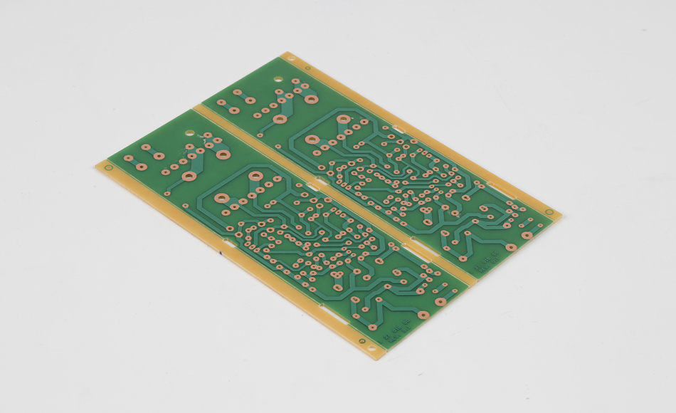
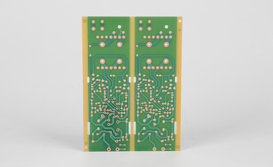
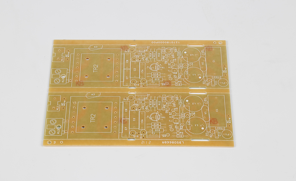
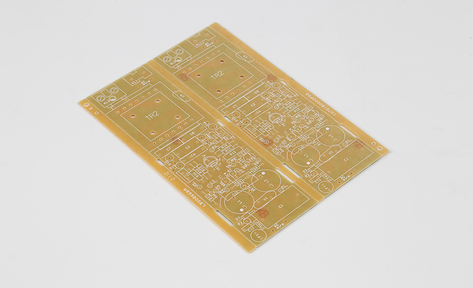
HA30 CEM3 Thermal Conductivity Specs represent a critical benchmark for mid-tier composite epoxy substrates, defining the material’s ability to transfer thermal energy and guiding its selection for applications where heat dissipation is essential but extreme performance (and associated costs) of high-end substrates are unnecessary. Unlike generic CEM3, which offers inconsistent thermal performance across batches, HA30 CEM3 is engineered to meet precise thermal conductivity specifications—ensuring predictable heat transfer in devices ranging from LED lighting drivers to industrial sensor modules. These specs are not mere technical details; they serve as a roadmap for engineers, helping them match the substrate’s thermal capabilities to the heat loads of their designs, avoid overengineering, and balance performance with cost.
In electronics where even small temperature increases can degrade component lifespan or cause performance drift (e.g., a 10°C rise in a power transistor can reduce its lifespan by 50%), HA30 CEM3’s well-defined thermal conductivity specs provide confidence in heat management. This article explores the significance of HA30 CEM3’s thermal conductivity specs, how they are engineered and validated, their role in optimizing application performance, and how they compare to alternative substrates. By focusing on “spec-driven thermal design,” it delivers unique insights distinct from prior discussions of CEM3’s scalability or distributed network use, ensuring relevance for engineers and procurement teams prioritizing predictable heat dissipation.
Thermal conductivity specs for HA30 CEM3 are more than a single number—they encompass a range of attributes that define how the material performs under real-world heat conditions. To leverage these specs effectively, it is critical to understand their components and what they signify for end applications.

HA30 CEM3’s thermal conductivity specs are typically structured to address three critical dimensions of heat transfer:
In-Plane Thermal Conductivity: Measures heat transfer along the substrate’s surface (X-Y axes), critical for spreading heat from localized sources (e.g., a power LED on a PCB). HA30 CEM3’s in-plane specs ensure uniform heat distribution across the board, preventing hot spots.
Through-Plane Thermal Conductivity: Measures heat transfer through the substrate’s thickness (Z-axis), essential for transferring heat to heat sinks or cooling layers below the PCB. HA30 CEM3’s through-plane specs ensure efficient vertical heat dissipation, a key requirement for high-power components.
Thermal Conductivity Stability Over Temperature: Defines how the material’s thermal conductivity changes across its operating temperature range (typically -30°C to 120°C). HA30 CEM3’s specs ensure minimal variation (≤10% change) in thermal performance, preventing unexpected heat buildup as the device heats up.
These specs are not arbitrary—they are tailored to mid-tier applications where heat loads range from 10W to 100W (e.g., LED drivers, small motor controllers), filling a gap between standard CEM3 (unreliable thermal performance) and high-end FR4 (overly high conductivity for mid-range needs).
Unlike generic CEM3, which may exhibit 15–20% variation in thermal conductivity across batches, HA30 CEM3’s specs enforce tight tolerances (typically ±5%). This consistency is critical for three reasons:
Predictable Design: Engineers can model heat flow accurately using the spec values, avoiding costly overdesign (e.g., adding unnecessary heat sinks) or underdesign (risking component failure).
Batch-to-Batch Reliability: For high-volume production (e.g., 100k+ units of a consumer LED bulb), consistent thermal specs ensure every PCB performs the same, reducing quality control issues and warranty claims.
Compliance with Industry Standards: HA30 CEM3’s thermal specs align with standards like IPC-4101 (specifications for base materials) and UL 94 (flammability), ensuring compatibility with global electronics regulations.

HA30 CEM3’s thermal conductivity specs are not achieved by chance—they result from targeted material modifications and manufacturing controls that optimize heat transfer while retaining CEM3’s cost and process advantages.
The core of HA30 CEM3’s thermal performance lies in its epoxy resin matrix, which is loaded with a hybrid of thermally conductive fillers tailored to meet the spec requirements:
Boron Nitride (BN) Nanoplates: These plate-like fillers (50–200nm thick) are aligned to enhance in-plane thermal conductivity. BN’s high thermal conductivity (up to 400 W/mK) and electrical insulation make it ideal for HA30 CEM3, as it boosts heat transfer without risking short circuits.
Aluminum Oxide (Al₂O₃) Microparticles: Spherical Al₂O₃ particles (1–5μm) fill gaps between BN nanoplates, improving through-plane thermal conductivity by creating continuous heat pathways through the resin.
Filler Loading Optimization: The ratio of BN to Al₂O₃ is precisely controlled (typically 60:40) to balance in-plane and through-plane performance, ensuring both meet HA30 CEM3’s spec targets. Overloading fillers is avoided, as it can compromise mechanical strength and processability.
HA30 CEM3’s epoxy resin is reformulated to support the filler network and enhance thermal stability:
Low-Viscosity Resin: The resin’s viscosity is reduced (via mild chemical modifiers) to ensure uniform filler dispersion during mixing. This prevents agglomeration, which would create thermal “dead zones” and fail to meet spec consistency.
Cross-Link Density Tuning: The resin’s cross-link structure is optimized to reduce phonon scattering (a primary cause of heat loss in polymers). A more ordered cross-link network allows heat-carrying phonons to travel longer distances, boosting thermal conductivity while maintaining mechanical rigidity.
HA30 CEM3’s glass fiber layers are not just for mechanical strength—they are engineered to support thermal transfer:
High-Thermal-Conductivity Glass Fibers: Instead of standard E-glass, HA30 CEM3 uses low-alkali E-glass fibers with higher silica content, which exhibit slightly higher thermal conductivity (0.9 W/mK vs. 0.8 W/mK for standard E-glass). This enhances in-plane heat spreading, aligning with the substrate’s spec targets.
Fiber Orientation Control: Woven outer layers are aligned to maximize heat flow along the substrate’s surface, while the non-woven core is densified to prevent air gaps that would reduce through-plane thermal conductivity.
Even with optimized materials, HA30 CEM3’s thermal specs require strict manufacturing controls to ensure batch-to-batch consistency:
Filler Dispersion Monitoring: In-line ultrasonic sensors track filler distribution during resin mixing, adjusting mixing speed or duration if agglomeration is detected. This ensures every batch meets the spec’s uniformity requirements.
Controlled Lamination: Lamination presses use precision temperature and pressure profiles (160°C–170°C, 25–30 psi) to ensure full resin impregnation of fibers and fillers. Under-impregnation would create voids, reducing thermal conductivity and failing spec targets.
Post-Cure Stabilization: HA30 CEM3 undergoes a 4-hour post-cure at 180°C to lock in the filler-resin network, ensuring thermal conductivity remains stable over the substrate’s lifespan. Without this step, thermal performance could drift over time, violating the spec’s stability requirements.

To ensure HA30 CEM3 meets its thermal conductivity specs, manufacturers and third-party labs conduct rigorous testing using methods approved by global standards bodies. These tests are designed to replicate real-world heat conditions and validate every dimension of the specs.
The ASTM D7984 standard uses the laser flash method to measure in-plane thermal conductivity:
Test Process: A thin HA30 CEM3 sample (1mm thick, 10mm × 10mm) is mounted on a heat sink. A short laser pulse is applied to one edge, and infrared sensors track the temperature rise across the sample’s surface. The rate of temperature spread is used to calculate in-plane thermal conductivity.
Spec Validation: HA30 CEM3’s test results must fall within the spec’s in-plane range (typically 0.8–1.0 W/mK) to pass. Samples that deviate by more than ±5% are rejected, ensuring batch consistency.
ASTM D5470 uses the guarded hot plate method to measure through-plane thermal conductivity:
Test Process: A HA30 CEM3 sample is sandwiched between two plates—one heated (at a constant temperature) and one cooled. Heat flow through the sample is measured, and through-plane thermal conductivity is calculated based on the temperature difference between the plates.
Spec Validation: HA30 CEM3’s through-plane results (typically 0.3–0.5 W/mK) must meet the spec’s targets. This ensures the substrate can transfer heat efficiently to heat sinks or underlying cooling layers.
To validate the spec’s thermal stability requirement, HA30 CEM3 is subjected to temperature cycling:
Test Process: Samples are cycled between -30°C and 120°C for 1,000 cycles. After each 200 cycles, thermal conductivity is remeasured using ASTM D7984 and D5470.
Spec Validation: The change in thermal conductivity must be ≤10% of the initial value. This ensures HA30 CEM3 maintains its heat transfer capabilities even as the device heats up and cools down during operation.
Beyond lab tests, HA30 CEM3 is validated under simulated application conditions:
Test Setup: A prototype PCB using HA30 CEM3 is mounted with a 50W power component (e.g., a LED driver IC). Thermal imaging cameras track hot spot temperatures over 1,000 hours of continuous operation.
Spec Alignment: The maximum hot spot temperature (typically ≤120°C) must align with the thermal conductivity specs—proving the substrate can handle real heat loads as predicted.

HA30 CEM3’s thermal conductivity specs are tailored to mid-tier applications where heat loads are moderate but consistent. Below are how these specs guide performance in three high-impact use cases:
LED drivers (10W–50W) generate heat that can degrade LED lifespan and brightness. HA30 CEM3’s specs address this by:
In-Plane Specs for Hot Spot Spreading: The 0.8–1.0 W/mK in-plane thermal conductivity spreads heat from the driver IC across the PCB, reducing hot spot temperatures by 15–20°C compared to standard CEM3. This aligns with the spec’s goal of uniform heat distribution.
Through-Plane Specs for Heat Sink Transfer: The 0.3–0.5 W/mK through-plane thermal conductivity efficiently transfers heat to the aluminum heat sink attached to the PCB’s backside. This ensures the driver IC remains within its safe operating temperature (≤85°C).
Result: HA30 CEM3’s specs enable LED drivers to operate reliably for 50,000+ hours—2x longer than those using standard CEM3—without requiring expensive heat sinks.
Industrial sensors (15W–30W) used in temperature monitoring or process control generate heat that can drift sensor accuracy. HA30 CEM3’s specs support this by:
Thermal Stability Specs for Consistent Performance: The ≤10% change in thermal conductivity over temperature ensures the sensor module’s PCB maintains stable heat transfer, even as the industrial environment fluctuates from 0°C to 100°C. This prevents temperature-induced drift in sensor readings (typically ≤±0.5°C).
In-Plane Specs for Component Isolation: The in-plane thermal conductivity spreads heat away from sensitive sensors (e.g., a thermistor) mounted near the power supply, ensuring the sensor remains at ambient temperature for accurate measurements.
Result: HA30 CEM3’s specs enable industrial sensors to maintain calibration for 3–5 years, reducing maintenance costs for factory operators.
Desktop or wall-mounted power supplies (30W–100W) generate heat during fast charging. HA30 CEM3’s specs address this by:
Through-Plane Specs for Cooling Efficiency: The through-plane thermal conductivity transfers heat to the power supply’s metal case, which acts as a passive heat sink. This eliminates the need for a fan, reducing noise and improving reliability.
Thermal Stability Specs for Long-Term Use: The stable thermal conductivity over temperature ensures the power supply maintains its efficiency (≥85%) even during extended fast-charging sessions (2–3 hours).
Result: HA30 CEM3’s specs enable power supplies to meet energy efficiency standards (e.g., 80 PLUS) while remaining cost-competitive with standard CEM3 designs.
To maximize the value of HA30 CEM3’s thermal conductivity specs, engineers should follow targeted design strategies that align with the spec’s strengths:
Cluster High-Heat Components: Place high-power components (e.g., ICs, resistors) in a central area of the PCB. HA30 CEM3’s in-plane thermal conductivity will spread heat evenly from this cluster, reducing hot spots.
Separate Heat-Sensitive Components: Position sensors or delicate ICs at least 10mm away from high-heat areas. The in-plane spec ensures heat does not reach these components, preventing performance drift.
Match Heat Sink Size to Through-Plane Performance: Use the through-plane thermal conductivity spec to calculate the required heat sink area. For example, a 50W component on HA30 CEM3 (0.4 W/mK through-plane) requires a 100cm² aluminum heat sink—smaller than the 150cm² needed for standard CEM3.
Use Thermal Vias for Vertical Heat Transfer: Add thermal vias (filled with conductive epoxy) in areas under high-heat components. These vias enhance through-plane heat transfer, complementing HA30 CEM3’s spec and reducing hot spot temperatures by an additional 10°C.
Simulate Heat Flow with Spec Values: Use thermal simulation software (e.g., ANSYS Icepak) and input HA30 CEM3’s thermal conductivity specs to model heat distribution. This predicts hot spots and ensures the design meets component temperature limits before prototyping.
Test Prototypes Against Specs: After building prototypes, measure thermal performance using thermal imaging and compare results to the spec. Any deviations (e.g., higher-than-expected hot spots) indicate design adjustments are needed (e.g., adding more thermal vias).

HA30 CEM3’s thermal conductivity specs position it uniquely in the mid-tier substrate market, offering a balance of performance and cost that alternatives cannot match. Below is how it compares to other substrates based on their thermal specs:
Thermal Conductivity Specs: Standard CEM3 has no defined thermal specs (typically 0.4–0.5 W/mK in-plane, 0.2–0.3 W/mK through-plane) with 15–20% batch variation. HA30 CEM3’s specs (0.8–1.0 W/mK in-plane, 0.3–0.5 W/mK through-plane) are 60–100% higher and more consistent.
Use Case: Standard CEM3 for low-power devices (e.g., remote controls), HA30 CEM3 for mid-power applications (e.g., LED drivers) where spec consistency is critical.
Thermal Conductivity Specs: High-thermal FR4 has specs of 1.0–1.2 W/mK in-plane and 0.5–0.7 W/mK through-plane but costs 40–60% more than HA30 CEM3.
Use Case: High-thermal FR4 for high-power devices (e.g., 100W+ industrial converters), HA30 CEM3 for mid-power applications where cost is a factor.
Thermal Conductivity Specs: MCPCBs have specs of 2–5 W/mK through-plane but conduct electricity (requiring insulation layers) and cost 3x more than HA30 CEM3.
Use Case: MCPCBs for ultra-high-power LEDs (100W+), HA30 CEM3 for mid-power LEDs (10W–50W) where electrical insulation is critical.
Thermal Conductivity Specs: Ceramics (e.g., alumina) have specs of 20–30 W/mK but are brittle, expensive (10x more than HA30 CEM3), and hard to process.
Use Case: Ceramics for power electronics (e.g., EV inverters), HA30 CEM3 for mid-tier applications where toughness and cost are priorities.
As mid-tier electronics demand higher power density (e.g., 5G small cells, EV auxiliary systems), HA30 CEM3’s thermal conductivity specs are evolving to meet new challenges:
Manufacturers are developing next-gen HA30 CEM3 variants with in-plane specs of 1.2–1.4 W/mK by integrating graphene nanoplatelets (GNP) into the filler mix. GNP’s ultra-high thermal conductivity (5,000 W/mK) boosts heat transfer without compromising electrical insulation, enabling HA30 CEM3 to handle 100W–150W heat loads.
Future HA30 CEM3 specs will combine thermal conductivity with other attributes, such as:
Low Dielectric Loss: Adding low-loss additives to the resin will reduce signal loss at high frequencies (up to 6 GHz), making HA30 CEM3 suitable for 5G power modules where both heat management and signal integrity are critical.
Flame Resistance: Enhancing UL 94 V-0 compliance while maintaining thermal specs will expand HA30 CEM3’s use in consumer electronics (e.g., laptop power supplies) with strict safety requirements.
To align with global sustainability goals, future HA30 CEM3 specs will include:
Recycled Filler Content: Using recycled aluminum oxide or boron nitride in the filler mix, maintaining thermal specs while reducing carbon emissions by 25%.
Bio-Based Resins: Epoxy resins derived from plant oils (e.g., castor oil) will replace petroleum-based resins, ensuring thermal conductivity specs remain unchanged while improving environmental impact.
HA30 CEM3 Thermal Conductivity Specs are more than technical benchmarks—they are a critical tool for engineers designing mid-tier electronics that demand predictable heat management. By defining in-plane, through-plane, and thermal stability performance, these specs ensure HA30 CEM3 can handle moderate heat loads while avoiding the cost of high-end substrates. Their consistency across batches and alignment with real-world application needs make HA30 CEM3 a reliable choice for LED drivers, industrial sensors, and consumer power supplies.
As electronics continue to shrink and pack more power into smaller form factors, HA30 CEM3’s thermal conductivity specs will evolve to meet new demands—higher conductivity, multi-functional performance, and sustainability. For engineers, these specs will remain a guiding principle, helping them balance heat management, cost, and performance in designs that power the next generation of mid-tier electronics. In a market where precision matters, HA30 CEM3’s thermal conductivity specs stand out as a testament to how well-defined standards can drive innovation and reliability.
Related Articles
CEM3 PCB Material Guide: ST210G Thermal Conductivity & LED Solutions
CEM3 PCB Material Guide for Industrial Electronics Applications
CEM3 PCB Manufacturer | The Best Cost-Effective Alternative to FR4
CEM3 PCB Manufacturer for Cost-Effective Industrial Electronics
CEM3-09HT Thermal Conductive PCB: Dual Advantages of High-Temp Resilience and Heat Dissipation
Countersink Holes in CEM3 PCB: Ensuring Structural Integrity and Assembly Precision
KB7150T High TG CEM3 Circuit Board: Reliable Performance for High-Temperature Electronics
LED Light CEM3 Circuit Board: Key Attributes and Applications in Modern Lighting Systems
Low CTE CEM3 Material for High Stability: Ensuring Precision in Dynamic Operational Environments
ST210G CEM3 Thermal Performance: Optimizing Heat Management for High-Power Electronic Devices
Thermal CEM3: Balancing Heat Management and Practicality in Electronics Substrates

Got project ready to assembly? Contact us: info@apollopcb.com


We're not around but we still want to hear from you! Leave us a note:

Leave Message to APOLLOPCB
