-
- PCB TYPE
- PRINTED CIRCUIT BOARD PROTOTYPE ALUMINUM PRINTED CIRCUIT BOARD R&F PCB FPC HIGH FREQUENCY PCB HIGH-TG PCB HEAVY COPPER PCB HDI PCB PCB FOR LIGHTING METAL CORE PCB
time:Aug 21. 2025, 11:54:10
0.8W/mK Thermal CEM-3 Material represents a significant advancement in the evolution of composite epoxy substrates, bridging the gap between traditional CEM-3’s moderate heat dissipation and high-performance materials like FR4 or metal-core PCBs. With a thermal conductivity of 0.8W/mK—nearly double that of standard CEM-3—this material addresses a critical pain point in electronics design: efficiently managing heat in devices where extreme thermal performance is unnecessary but improved dissipation is essential. Targeting applications such as LED drivers, small motor controllers, and IoT gateways, 0.8W/mK Thermal CEM-3 retains CEM-3’s core advantages—cost-effectiveness, mechanical stability, and ease of manufacturing—while expanding its utility into heat-sensitive environments. This article examines the material science behind its enhanced thermal properties, manufacturing innovations, practical applications, and how it balances performance and affordability to meet the demands of modern electronics.
The leap from standard CEM-3’s typical thermal conductivity (0.4–0.5W/mK) to 0.8W/mK is rooted in deliberate modifications to its composition and structure, without sacrificing the material’s inherent benefits:
At the heart of 0.8W/mK Thermal CEM-3 is the strategic addition of thermally conductive nanofillers—typically aluminum oxide (Al₂O₃), boron nitride (BN), or silicon carbide (SiC)—dispersed within the epoxy resin matrix. These nanoparticles create a network of heat-conducting pathways through the otherwise insulating polymer, allowing thermal energy to transfer more efficiently across the material. Unlike larger fillers, which can weaken the PCB or disrupt electrical insulation, nanofillers (50–200nm in diameter) distribute evenly, maintaining CEM-3’s mechanical strength and dielectric properties. The optimal loading of these fillers—typically 15–25% by weight—strikes a balance: sufficient to boost thermal conductivity to 0.8W/mK without compromising resin flow during lamination, a critical factor for consistent manufacturing.
Standard CEM-3’s thermal performance is limited by poor heat transfer at the interface between glass fibers and epoxy resin, where air gaps or weak bonding create thermal resistance. 0.8W/mK Thermal CEM-3 addresses this with a coupling agent—usually a silane-based compound—that improves adhesion between the fibers and resin. This agent forms chemical bonds across the interface, reducing thermal resistance and enabling more efficient heat flow from the resin to the glass fibers, which act as secondary heat-dissipating channels. The result is a 30% reduction in interface thermal resistance compared to standard CEM-3, contributing significantly to the overall conductivity boost.
The epoxy resin itself is modified to enhance thermal stability and reduce phonon scattering—the primary mechanism by which heat is lost in polymers. By adjusting the resin’s cross-link density and molecular weight distribution, manufacturers create a more ordered structure that allows heat-carrying phonons to travel longer distances before colliding with imperfections. This structural refinement, combined with nanofillers, ensures that thermal energy is conducted rather than trapped as heat in the material.
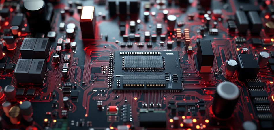
0.8W/mK Thermal CEM-3’s enhanced thermal conductivity delivers tangible benefits in devices where heat management directly impacts performance, reliability, and longevity:
Heat is a primary driver of component degradation, particularly in semiconductors, capacitors, and connectors. By dissipating heat 60–80% more effectively than standard CEM-3, 0.8W/mK Thermal CEM-3 reduces operating temperatures in critical components by 10–15°C. In LED drivers, for example, this temperature reduction can extend the lifespan of electrolytic capacitors—often the shortest-lived component—by 2–3x, lowering maintenance costs in lighting systems.
The ability to dissipate more heat allows 0.8W/mK Thermal CEM-3 to support higher power densities than standard CEM-3. Devices like small motor controllers or DC-DC converters can operate at 15–20% higher power levels without exceeding safe temperature thresholds, enabling more compact designs by reducing the need for bulky heat sinks. In smart home hubs, this means integrating more processing power into the same form factor, supporting advanced features like AI-driven automation.
Thermal cycling—repeated expansion and contraction due to temperature fluctuations—creates mechanical stress that can cause solder joint fatigue or PCB warping. 0.8W/mK Thermal CEM-3’s more uniform heat distribution minimizes temperature gradients across the PCB, reducing differential expansion between components and the substrate. This is particularly valuable in automotive electronics, where under-hood or cabin temperature swings can stress standard CEM-3 PCBs, leading to premature failure.
While 0.8W/mK Thermal CEM-3 costs 10–15% more than standard CEM-3, it remains 30–40% cheaper than FR4 or metal-core PCBs (MCPCBs) with similar thermal conductivity. This makes it an ideal choice for mid-range devices where premium materials are unjustified but improved heat management is necessary. For manufacturers producing millions of units—such as consumer LED bulbs or IoT sensors—the cost savings add up significantly without compromising performance.
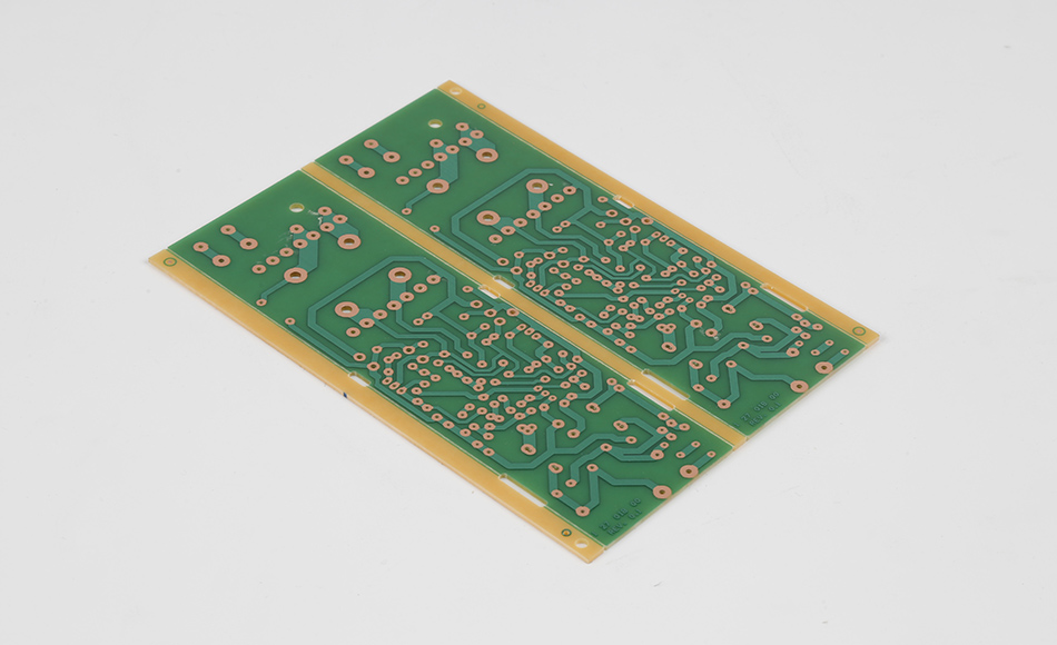
Producing 0.8W/mK Thermal CEM-3 requires adjustments to standard CEM-3 manufacturing processes to accommodate its modified composition, ensuring consistent quality and performance:
Uneven distribution of nanofillers can create hot spots or weak points in the material, undermining its thermal and mechanical properties. Manufacturers use high-shear mixing or ultrasonic dispersion techniques to ensure fillers are uniformly distributed throughout the epoxy resin. In-line rheology monitoring—measuring the resin’s viscosity—verifies dispersion quality, with deviations triggering adjustments to mixing speed or duration. This precision is critical: even small agglomerations of nanofillers can reduce thermal conductivity by 10–15% in localized areas.
The addition of nanofillers increases the epoxy resin’s viscosity, requiring adjustments to lamination parameters to ensure proper impregnation of the glass fibers. Manufacturers typically raise lamination temperatures by 5–10°C (to 160–175°C) and extend dwell times by 10–15% to allow the resin to flow into the fiber matrix fully. Pressure is also carefully controlled—typically 20–30 psi—to prevent air entrapment, which would create thermal and mechanical weak points. These adjustments ensure the final material retains its structural integrity and thermal conductivity.
Standard CEM-3 quality checks (e.g., dielectric strength, flexural testing) are augmented with thermal conductivity verification for 0.8W/mK variants. Techniques like the laser flash method—measuring how quickly heat propagates through a sample—validate that thermal conductivity meets the 0.8W/mK specification across production batches. Additionally, infrared thermography inspects heat distribution under load, ensuring no localized defects compromise performance.
Despite its modifications, 0.8W/mK Thermal CEM-3 remains compatible with standard PCB manufacturing steps, including drilling, etching, and solder masking. This is critical for adoption, as manufacturers need not retool or invest in specialized equipment. The material’s thermal stability also allows it to withstand reflow soldering temperatures (up to 260°C) without degradation, ensuring compatibility with surface-mount technology (SMT) assembly lines.
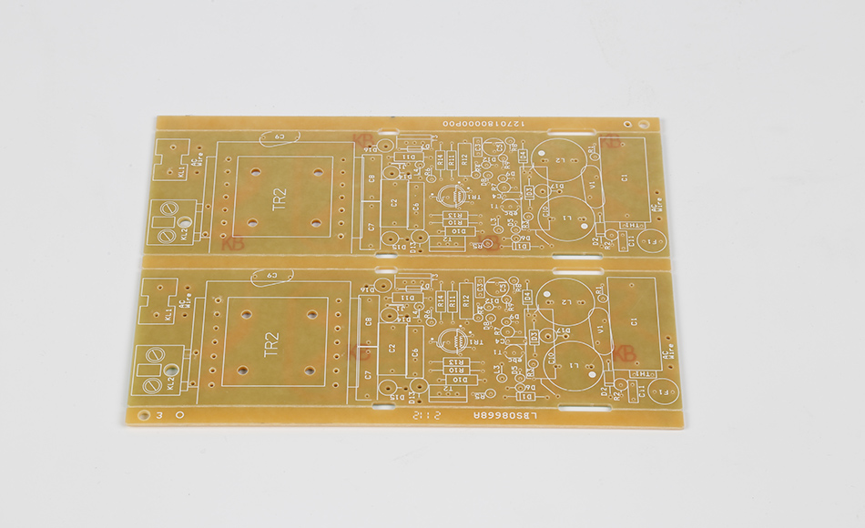
0.8W/mK Thermal CEM-3 excels in applications where heat generation is moderate but impactful, filling a gap between standard CEM-3 and high-performance substrates:
Commercial Downlights: These fixtures operate at 15–50W, generating enough heat to degrade standard CEM-3 over time. 0.8W/mK Thermal CEM-3 dissipates heat efficiently, extending lifespans and reducing flicker caused by overheating drivers.
Automotive Headlights: LED drivers in headlights face tight space constraints and temperature swings. 0.8W/mK Thermal CEM-3’s improved conductivity eliminates the need for expensive MCPCBs while ensuring reliable performance in engine bay conditions.
Motor Controllers: Small AC/DC motor controllers (e.g., in conveyor systems) generate steady heat during operation. 0.8W/mK Thermal CEM-3 prevents overheating, ensuring consistent speed regulation and reducing downtime.
Power Supplies: Desktop or wall-mounted power supplies (30–100W) benefit from the material’s ability to handle higher power densities, enabling smaller, more energy-efficient designs.
Smart Thermostats: These devices integrate processing units and wireless modules that generate continuous heat. 0.8W/mK Thermal CEM-3 prevents thermal throttling, ensuring responsive performance and accurate temperature sensing.
Security Cameras: Outdoor cameras with IR LEDs generate heat that can fog lenses or degrade image sensors. The material’s heat dissipation keeps components cool, maintaining image quality in 24/7 operation.
Gaming Accessories: High-performance gaming mice or keyboards with RGB lighting use 0.8W/mK Thermal CEM-3 to manage heat from LEDs and microcontrollers, preventing discomfort during extended use.
Portable Chargers: Fast-charging power banks (18–65W) generate significant heat during operation. The material ensures safe, efficient charging without overheating.
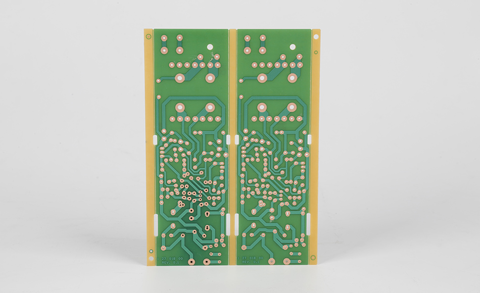
0.8W/mK Thermal CEM-3 occupies a unique niche in the thermal management landscape, offering distinct advantages over other materials in specific scenarios:
Standard CEM-3 (0.4–0.5W/mK) is sufficient for low-power devices like remote controls or basic sensors but fails in applications with moderate heat generation. 0.8W/mK Thermal CEM-3 delivers 60–80% better heat dissipation, making it suitable for devices operating at 10–100W—all while retaining CEM-3’s cost and manufacturing benefits.
FR4 typically offers 0.2–0.3W/mK thermal conductivity in standard forms, though high-performance variants reach 0.8–1.0W/mK. However, these high-performance FR4s cost 30–50% more than 0.8W/mK Thermal CEM-3, making them overkill for mid-range applications. For example, a 30W LED driver performs identically on 0.8W/mK Thermal CEM-3 as on high-performance FR4 but at a lower cost.
MCPCBs (2–5W/mK) excel in high-power applications like 100+W LED floodlights but are heavier, more expensive, and harder to machine than 0.8W/mK Thermal CEM-3. For devices under 100W—such as 50W smart streetlights—0.8W/mK Thermal CEM-3 provides sufficient cooling at 1/3 the cost of MCPCBs.
Ceramic substrates (e.g., alumina, 20–30W/mK) offer superior thermal conductivity but are brittle, expensive, and difficult to integrate with standard PCB processes. They are reserved for extreme applications like power electronics, while 0.8W/mK Thermal CEM-3 serves mid-range needs more practically.
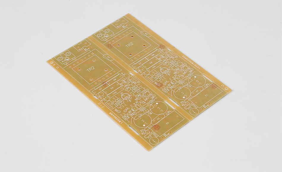
0.8W/mK Thermal CEM-3 is just the beginning, with ongoing research aiming to push thermal conductivity higher while maintaining cost and manufacturability:
Combining different nanofillers—e.g., boron nitride (high thermal conductivity) and carbon nanotubes (excellent thermal pathways)—could create synergistic effects, potentially pushing thermal conductivity to 1.0–1.2W/mK. Early trials show these hybrid systems maintain electrical insulation, making them viable for high-voltage applications.
Manufacturers are exploring bio-based or recycled fillers—such as rice husk ash (rich in silica)—as alternatives to synthetic nanofillers. These sustainable options reduce the material’s carbon footprint while maintaining thermal performance, aligning with the electronics industry’s shift toward eco-friendly practices.
Laminating 0.8W/mK Thermal CEM-3 with thin copper or graphite layers could create “thermal sandwiches” that combine the material’s base conductivity with enhanced lateral heat spreading. This would be particularly valuable in devices with concentrated heat sources, like power transistors, ensuring uniform temperature distribution.
0.8W/mK Thermal CEM-3 Material represents a pivotal innovation in mid-range PCB substrates, proving that enhanced thermal performance need not come at a premium. By leveraging nanofiller technology, interface engineering, and optimized manufacturing, it delivers nearly double the thermal conductivity of standard CEM-3 while retaining its cost-effectiveness and process compatibility. This makes it an ideal choice for a wide range of applications—from LED drivers to IoT devices—where moderate heat generation threatens performance but high-end materials are unnecessary. As electronics continue to shrink and pack more power into smaller form factors, 0.8W/mK Thermal CEM-3 will play an increasingly critical role, enabling reliable, efficient designs that balance performance, cost, and sustainability. For engineers and manufacturers, it represents a strategic material choice: one that meets today’s thermal challenges without compromising tomorrow’s innovation.

Got project ready to assembly? Contact us: info@apollopcb.com


We're not around but we still want to hear from you! Leave us a note:

Leave Message to APOLLOPCB
