-
- PCB TYPE
- PRINTED CIRCUIT BOARD PROTOTYPE ALUMINUM PRINTED CIRCUIT BOARD R&F PCB FPC HIGH FREQUENCY PCB HIGH-TG PCB HEAVY COPPER PCB HDI PCB PCB FOR LIGHTING METAL CORE PCB
time:Aug 20. 2025, 16:37:51
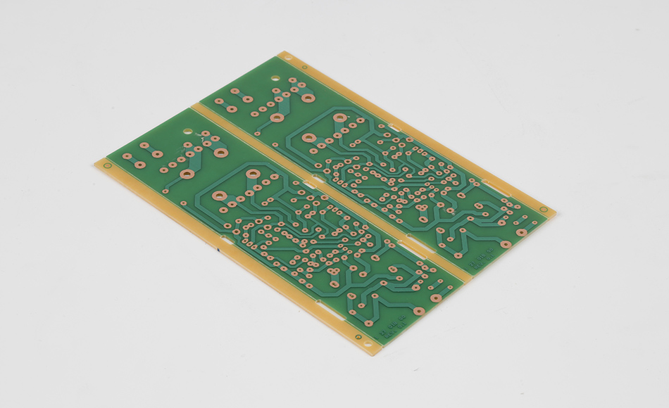
Counterbore Holes in CEM3 PCB serve as foundational elements in electronic assembly, providing structured recesses that enable secure, flush mounting of components, fasteners, and hardware. Unlike countersinks, which feature a conical shape to accommodate angled fastener heads, counterbores are cylindrical, flat-bottomed recesses designed to seat the head of a fastener or the base of a component entirely below the PCB surface, with the shank or lead extending through a smaller through-hole. In CEM3 PCBs—valued for their balanced blend of affordability, mechanical resilience, and electrical insulation—counterbore holes address critical challenges in device design, from reducing profile height to distributing stress evenly across the substrate. This article examines the core functions, manufacturing considerations, quality standards, and diverse applications of counterbore holes in CEM3 PCBs, highlighting their role as unsung enablers of reliable, compact electronic assemblies.
Counterbore holes in CEM3 PCBs fulfill multiple critical roles that extend beyond simple component placement, directly influencing device performance, durability, and design flexibility:
The primary purpose of a counterbore is to allow components or fasteners to sit flush with the PCB surface, eliminating protrusions that could interfere with device housings, adjacent components, or user interaction. In CEM3 PCBs used in compact devices—such as smartwatches or handheld scanners—this flush mounting reduces the overall profile by up to 30%, enabling sleeker, more ergonomic designs. For example, a counterbore housing a battery connector in a CEM3-based fitness tracker ensures the device lies flat against the wrist, enhancing comfort and usability.
CEM3’s layered structure—non-woven glass core and woven glass outer layers—responds well to evenly distributed pressure, but concentrated stress (e.g., from a fastener head pressing against a small area) can cause delamination or cracking. Counterbore holes spread this stress across a larger surface area, leveraging the material’s glass fiber reinforcement to withstand tension and compression. This is particularly important in vibration-prone environments, such as industrial machinery or automotive electronics, where repeated stress could weaken non-recessed connections over time.
Many electronic components, from connectors to sensors, require exact positioning to function correctly. Counterbore holes act as physical guides during assembly, ensuring these components are centered and seated at the correct depth. In high-density CEM3 PCBs—such as those in home automation controllers—this alignment prevents short circuits caused by misaligned parts and ensures consistent electrical contact. A counterbore securing an HDMI connector, for instance, guarantees that the port aligns perfectly with the device chassis, preventing damage during insertion.
Flush-mounted components, enabled by counterbores, minimize gaps where dust, moisture, or debris can accumulate. In CEM3 PCBs deployed in harsh environments—such as kitchen appliances or outdoor sensors—this reduces the risk of corrosion, insulation breakdown, or short circuits. The counterbore’s cylindrical walls also help channel liquids away from sensitive components, adding a passive defense against spills or condensation.
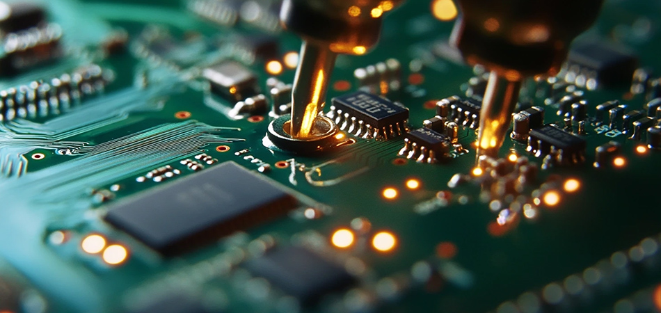
CEM3’s unique composition presents distinct challenges when machining counterbore holes, requiring specialized approaches to avoid defects that could compromise performance:
CEM3’s construction creates variations in density and hardness that affect how counterbores are formed. The non-woven glass core, with its porous, randomly oriented fibers, is softer and more prone to tearing or collapsing during cutting, while the woven outer layers—dense and tightly packed—resist tool penetration, potentially causing uneven recess walls. This mismatch can result in “stepped” counterbores, where the core material is removed faster than the outer layers, leaving a ridge that prevents components from seating flush.
The epoxy resin binding CEM3’s glass fibers is sensitive to friction-generated heat during machining. Excessive heat can soften the resin, causing it to flow into the counterbore and create burrs or reduce the recess diameter. This is especially problematic in high-speed production, where prolonged tool contact amplifies thermal buildup. Softened resin may also adhere to cutting tools, leading to uneven surfaces or debris accumulation in the counterbore.
Glass fibers in CEM3 are abrasive and brittle, making them prone to fraying if cut with dull or inappropriate tools. Frayed fibers can protrude into the counterbore, interfering with component seating or creating electrical insulation risks (e.g., shorting against conductive parts). In extreme cases, fraying can weaken the counterbore’s edges, increasing the risk of cracking under stress.
CEM3 PCBs exhibit slight variations in thickness and fiber density across production batches, making consistent counterbore dimensions challenging to maintain. A counterbore that is too deep may weaken the PCB by removing excess material, while one that is too shallow fails to seat components flush. Achieving tight tolerances (typically ±0.05mm for depth) requires careful calibration of cutting tools and processes.
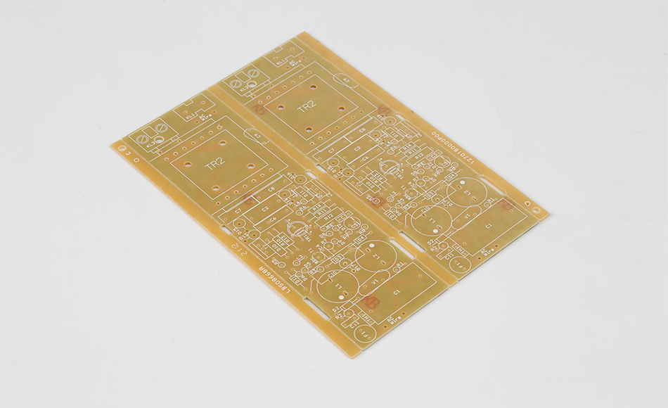
Producing high-quality counterbore holes in CEM3 requires a combination of specialized tooling, optimized parameters, and material-specific adjustments to overcome the substrate’s unique challenges:
Carbide End Mills: Carbide tools offer superior hardness and wear resistance, making them ideal for cutting through CEM3’s glass fibers. Their sharp, rigid edges minimize fraying and ensure clean, straight counterbore walls.
Flat-Bottom Design: Tools with perfectly flat cutting surfaces are essential for creating the flat-bottomed recesses required for flush component mounting. Any curvature in the tool tip would transfer to the counterbore, preventing proper seating.
Variable Flute Geometry: End mills with variable flute spacing reduce vibration during cutting, preventing uneven recesses caused by tool chatter. This is particularly useful for CEM3, where fiber density variations can amplify vibration.
Controlled Spindle Speeds: Operating at 15,000–25,000 RPM balances cutting efficiency with heat generation, ensuring the epoxy resin remains stable while glass fibers are sheared cleanly. Higher speeds risk overheating, while lower speeds increase fiber fraying.
Stepwise Depth Cutting: Instead of machining the full counterbore depth in a single pass, tools make multiple shallow passes (0.1–0.2mm each). This reduces pressure on the CEM3 material, minimizing tearing in the non-woven core and ensuring a flat bottom.
Coolant Delivery: Directed mist coolant is applied to the cutting area to dissipate heat and flush away glass fiber debris. The coolant is formulated to be compatible with CEM3’s epoxy resin, avoiding chemical reactions that could weaken the substrate or leave residues in the counterbore.
Pilot Hole Drilling: A small pilot hole (typically 50–70% of the final through-hole diameter) is drilled first to guide the counterbore tool, ensuring concentricity between the counterbore and the through-hole. This step is critical for preventing misalignment in CEM3, where fiber density variations can cause tool drift.
Counterbore Machining: The counterbore tool is centered on the pilot hole and advanced to the required depth, creating the cylindrical recess. This is followed by drilling the full-diameter through-hole to avoid damaging the counterbore edges during final hole formation.
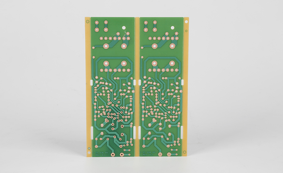
Ensuring the integrity of counterbore holes in CEM3 PCBs requires rigorous inspection to verify dimensional accuracy, surface quality, and structural soundness:
Optical Profilometry: This non-contact method uses laser scanning to measure counterbore diameter, depth, and bottom flatness with micron-level precision. It can detect even minor deviations—such as a 0.03mm variation in depth—that could affect component fit.
Coordinate Measuring Machines (CMMs): CMMs with touch probes physically map the counterbore’s geometry, verifying concentricity with the through-hole and ensuring the recess is perpendicular to the PCB surface. This is critical for high-reliability applications like medical devices.
Automated Visual Inspection (AVI): High-resolution cameras check counterbore walls and bottoms for defects like frayed fibers, resin burrs, or uneven surfaces. AVI systems flag anomalies in real time, preventing defective PCBs from proceeding to assembly.
Tactile Profiling: For critical applications, a stylus-based profilometer measures surface roughness in the counterbore, ensuring it meets specifications (typically Ra < 1.6μm) to avoid interfering with component seating.
Cross-Section Analysis: Microscopic examination of sliced CEM3 samples reveals whether counterbore machining caused delamination between layers or fiber damage. This helps identify issues like excessive heat or tool pressure during manufacturing.
Load Testing: Samples are subjected to simulated operational loads (e.g., clamping force from fasteners) to verify that counterbores can withstand stress without cracking or deforming. This is particularly important for CEM3 PCBs in industrial or automotive applications.
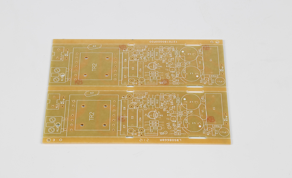
Counterbore holes in CEM3 PCBs are integral to a wide range of devices, each leveraging their unique benefits to address specific design challenges:
Wearables: Smartwatches and fitness trackers use counterbores in CEM3 PCBs to mount sensors, batteries, and display modules flush with the device surface, ensuring a comfortable fit on the wrist.
Home Appliances: Refrigerator control boards and microwave PCBs employ counterbores to secure wiring harness connectors, preventing protrusions that could interfere with appliance doors or internal components.
Control Panels: CEM3 PCBs in factory control systems use counterbores to mount membrane switches and LED indicators, ensuring these components withstand vibration from nearby machinery without loosening.
Robotics: Small robotic arms and drones rely on counterbores in CEM3 PCBs to mount motors and position sensors, where low-profile design and precise alignment are critical for movement accuracy.
Portable Diagnostics: Handheld blood glucose monitors and pulse oximeters use counterbores to secure test strip connectors and display screens, ensuring reliability in clinical settings where precision is paramount.
Patient Monitors: Counterbores in CEM3 PCBs for bedside monitors protect wiring harnesses from accidental damage, with flush-mounted connectors reducing the risk of disconnections during patient care.
In-Cabin Systems: Infotainment and climate control PCBs use counterbores to mount USB ports and control knobs, withstanding temperature fluctuations and vehicle vibrations.
Sensor Modules: Parking assist and lane departure sensors leverage counterbores in CEM3 PCBs to maintain alignment, ensuring accurate readings critical for driver safety.
Designers and manufacturers can optimize counterbore holes in CEM3 PCBs by following these guidelines to ensure performance, reliability, and manufacturability:
Match Counterbore Size to Component Requirements: Ensure the counterbore diameter and depth accommodate the specific component or fastener, with a 0.1–0.2mm clearance to account for manufacturing tolerances.
Avoid Placement Near PCB Edges: Position counterbores at least 1.5 times their diameter away from the PCB edge to prevent weakening the substrate, especially in thin CEM3 PCBs (≤1.0mm).
Integrate Clearance Zones: Maintain a 0.3mm gap between counterbores and copper traces or solder masks to avoid damaging conductive paths during machining.
Material Batch Testing: Test counterboring parameters on samples from each CEM3 batch, as fiber content and resin viscosity can vary, affecting cutting performance. Adjust tool speeds or feed rates based on results.
Tool Maintenance Schedules: Regularly inspect and replace cutting tools to prevent dullness, which can cause fiber fraying or uneven counterbores. This is especially critical in high-volume production.
Use Compatible Fasteners: Select fasteners with heads designed to fit the counterbore (e.g., flat-head or pan-head screws) to ensure flush mounting and even stress distribution.
Control Torque During Installation: Apply consistent torque (using calibrated tools) to fasteners in counterbores to avoid over-tightening, which can crack the CEM3 material or deform the recess.
Advancements in manufacturing and material science are enhancing the precision and efficiency of counterbore holes in CEM3 PCBs, expanding their capabilities and applications:
Fiber laser systems are emerging as a viable option for creating small counterbores (≤1.0mm diameter) in CEM3, offering non-contact cutting that minimizes heat damage to the epoxy resin. Lasers can achieve extremely consistent dimensions and smooth surfaces, reducing fiber fraying and improving component fit. While currently more expensive than mechanical methods, laser machining is becoming cost-effective for high-precision applications like micro-sensors.
Machine learning algorithms are being used to analyze real-time data from cutting sensors, adjusting speed, feed rate, and coolant flow to optimize counterbore quality for each CEM3 batch. By predicting how material variations affect machining, these systems reduce defects and improve yield, particularly in high-volume production.
Manufacturers are adopting eco-friendly coolants and carbide tools with recycled materials to reduce the environmental impact of counterbore production. These innovations align with the growing demand for sustainable electronics manufacturing, ensuring CEM3 PCBs remain an environmentally responsible choice.
Counterbore Holes in CEM3 PCB are essential components in modern electronics, enabling secure, flush component mounting that enhances device performance, durability, and design flexibility. By addressing the unique challenges of CEM3’s layered structure through specialized tooling, optimized processes, and rigorous quality control, manufacturers ensure these recesses meet the demands of diverse applications—from consumer wearables to industrial machinery. As technology advances, counterbore holes in CEM3 PCBs will continue to evolve, leveraging innovations like laser machining and AI-driven optimization to meet the needs of increasingly compact, high-reliability electronics. For engineers and manufacturers, understanding the nuances of counterbore design and production is key to creating assemblies that balance functionality, cost, and durability in a rapidly changing industry.
Related Articles
Aluminum & Flexible PCB Solutions | High-Thermal & Flex Sourcing
PCB Assembly & Manufacturing Costs Guide | Turnkey PCB & FPCB Solutions
CEM3 PCB Material Guide: ST210G Thermal Conductivity & LED Solutions
CEM3 PCB Material Guide for Industrial Electronics Applications
CEM3 PCB Manufacturer | The Best Cost-Effective Alternative to FR4
CEM3 PCB Manufacturer for Cost-Effective Industrial Electronics
CEM3-09HT Thermal Conductive PCB: Dual Advantages of High-Temp Resilience and Heat Dissipation
Countersink Holes in CEM3 PCB: Ensuring Structural Integrity and Assembly Precision
KB7150T High TG CEM3 Circuit Board: Reliable Performance for High-Temperature Electronics
HA30 CEM3 Thermal Conductivity Specs: Guiding Heat Management in Mid-Tier Electronics
LED Light CEM3 Circuit Board: Key Attributes and Applications in Modern Lighting Systems
Low CTE CEM3 Material for High Stability: Ensuring Precision in Dynamic Operational Environments
ST210G CEM3 Thermal Performance: Optimizing Heat Management for High-Power Electronic Devices
Thermal CEM3: Balancing Heat Management and Practicality in Electronics Substrates

Got project ready to assembly? Contact us: info@apollopcb.com


We're not around but we still want to hear from you! Leave us a note:

Leave Message to APOLLOPCB
