-
- PCB TYPE
- PRINTED CIRCUIT BOARD PROTOTYPE ALUMINUM PRINTED CIRCUIT BOARD R&F PCB FPC HIGH FREQUENCY PCB HIGH-TG PCB HEAVY COPPER PCB HDI PCB PCB FOR LIGHTING METAL CORE PCB
time:Aug 04. 2025, 11:44:58
FR4 has established itself as the most widely used base material for rigid printed circuit boards (PCBs) across industries, from consumer electronics to industrial automation. Its dominance stems from a unique combination of electrical insulation, mechanical strength, thermal stability, and cost-effectiveness. This specification sheet explores the technical nuances of FR4, offering engineers, designers, and manufacturers a detailed reference to understand its properties, performance limits, and application suitability. Unlike generic overviews, this guide delves into material behavior under varying conditions, compliance standards, and advanced considerations that impact PCB reliability.
FR4 is a glass-reinforced epoxy laminate, classified as a thermoset composite within the copper-clad laminate (CCL) family. The "FR" in its name stands for "flame-retardant," a critical safety feature derived from additives that prevent sustained combustion. Its composition is a carefully engineered matrix designed to balance structural integrity and functional performance:
Epoxy Resin: The primary binding agent, responsible for adhesion between layers, electrical insulation, and resistance to chemicals. Most FR4 formulations use bisphenol-A epoxy resins, though brominated variants are common to enhance flame retardancy. Modified epoxies may include phenolic hardeners to adjust thermal properties, such as glass transition temperature (Tg).
Glass Fiber Reinforcement: Typically E-glass (alumino-borosilicate glass) woven into fabrics of varying thicknesses (e.g., 1080, 2116, 7628 weaves). The glass fiber provides mechanical rigidity, dimensional stability, and resistance to warpage during manufacturing and operation. The weave pattern influences properties like flexural strength and moisture absorption—thicker weaves offer higher strength but may increase dielectric loss at high frequencies.
Copper Foil: Bonded to one or both surfaces of the laminate, serving as the conductive layer for circuit traces. Copper thickness ranges from 0.5 ounces (17.5 μm) for fine-pitch designs to 4 ounces (140 μm) or more for high-current applications. Electrodeposited (ED) copper is standard for most PCBs, while rolled copper is used in specialized cases requiring better ductility, such as flexible-rigid hybrids.
Additives: Flame retardants (e.g., tetrabromobisphenol A) to meet UL94 V-0 standards; fillers (e.g., silica) to reduce thermal expansion; and coupling agents (e.g., silanes) to improve adhesion between the epoxy resin and glass fibers, minimizing delamination risks.
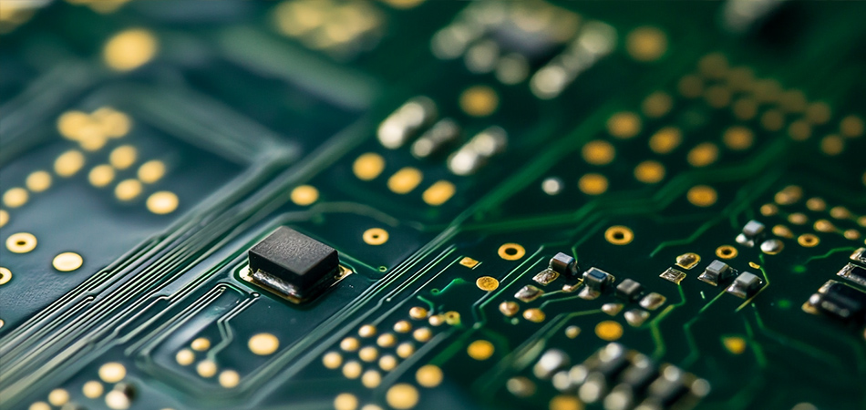
The physical properties of FR4 directly influence PCB manufacturability, handling, and long-term reliability. These characteristics are tightly controlled during production to ensure consistency across batches:
Density: Typically ranges between 1.8 and 2.0 g/cm³, a value that balances structural robustness with weight efficiency—critical for applications like aerospace or portable electronics where weight is a constraint.
Thickness Variability: Available in nominal thicknesses from 0.031 inches (0.79 mm) to 0.250 inches (6.35 mm), with tighter tolerances (±5% to ±10%) required for impedance-controlled designs. Thickness uniformity across the laminate is essential to prevent signal distortion in high-speed PCBs.
Surface Finish Compatibility: FR4 substrates are compatible with all common PCB surface finishes, including hot-air solder leveling (HASL), electroless nickel immersion gold (ENIG), organic solderability preservatives (OSP), and immersion tin. The surface texture of the laminate, often roughened during manufacturing, ensures strong adhesion between the copper and subsequent finishes.
Moisture Absorption: A critical parameter for humid environments. Standard FR4 absorbs ≤0.15% of its weight when immersed in water at 23°C for 24 hours (per IPC-4101). Low-moisture variants, modified with hydrophobic additives, reduce this to ≤0.12%, making them suitable for outdoor or marine applications where condensation is common.
Color: Naturally amber or brown, though black FR4 is available for applications requiring light blocking (e.g., camera modules or sensors where stray light could interfere with performance).
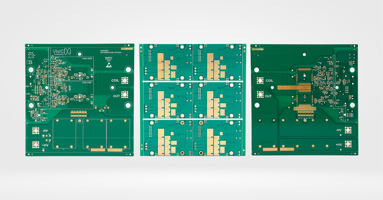
As an insulating material, FR4’s electrical properties are paramount for maintaining signal integrity, minimizing losses, and preventing short circuits. These properties vary with frequency, temperature, and humidity, requiring careful consideration during design:
Dielectric Constant (Dk): A measure of a material’s ability to store electrical energy in an electric field. For standard FR4, Dk ranges from 4.2 to 4.7 at 1 MHz. However, it increases with frequency—at 10 GHz, values typically rise to 4.5–5.0. High-frequency applications (e.g., 5G base stations, radar systems) often use low-Dk FR4 variants (3.8–4.2 at 1 MHz) to reduce signal delay and attenuation.
Dissipation Factor (Df): Indicates energy loss as heat in an alternating electric field. Standard FR4 has a Df of ≤0.02 at 1 MHz, but this increases with frequency and temperature. For high-speed signals (e.g., 10 Gbps Ethernet), low-Df FR4 (≤0.015 at 1 MHz) is preferred to minimize signal degradation.
Dielectric Strength: The maximum electric field the material can withstand before breakdown. FR4 typically exhibits dielectric strength ≥20 kV/mm (per ASTM D149), ensuring it resists arcing even in high-voltage applications like power supplies or industrial motor controllers.
Insulation Resistance: Measures resistance to leakage current. Volume resistivity (resistance through the material) is ≥10¹⁴ Ω·cm (per IPC-TM-650 2.5.17), while surface resistivity (resistance across the surface) is ≥10¹³ Ω. These values drop slightly in humid conditions, emphasizing the need for proper conformal coating in damp environments.
Signal Propagation: The speed of signal transmission in FR4 is approximately 1.5 ns per inch for 50Ω microstrip traces, a key metric for timing-sensitive designs. Variations in Dk across the laminate can cause signal skew, making material consistency critical for multi-layer PCBs with high-speed parallel buses.
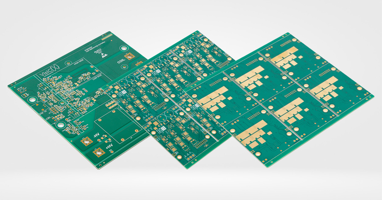
FR4’s mechanical strength ensures PCBs withstand manufacturing stresses (e.g., drilling, routing, soldering) and operational loads (e.g., vibration, thermal cycling). These properties are anisotropic, meaning they vary with the direction of the glass fiber weave:
Tensile Strength: The maximum stress the material can withstand before breaking. Along the fiber direction, FR4 exhibits tensile strength ≥400 MPa, while transverse strength (perpendicular to the weave) is slightly lower. This directional difference is critical for designing PCBs subject to mechanical stress, such as those in automotive or aerospace applications where vibration is common.
Flexural Strength: Measures resistance to bending. At room temperature, FR4 typically achieves ≥500 MPa, dropping to ≥300 MPa at 125°C—still sufficient for most operational environments. Flexural modulus (stiffness) ranges from 20 to 25 GPa, ensuring rigidity in rigid PCB designs.
Peel Strength: The force required to separate the copper foil from the laminate. For 1 oz copper, peel strength is ≥1.0 N/mm (per IPC-TM-650 2.4.8), a critical factor in preventing trace lifting during soldering or thermal cycling. Lower peel strength can lead to reliability issues, especially in PCBs with fine-pitch components.
Impact Resistance: Charpy impact strength (unnotched) is ≥15 kJ/m², making FR4 resistant to accidental drops or mechanical shocks—important for consumer electronics like smartphones or laptops.
Dimensional Stability: Minimal change in size with temperature or humidity. Below its glass transition temperature (Tg), FR4 exhibits low dimensional change, with variations ≤0.1% under normal conditions. This stability is essential for maintaining alignment in multi-layer PCBs, where layer-to-layer registration errors can cause short circuits or open traces.
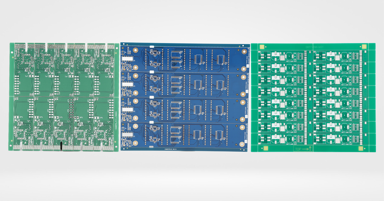
Thermal properties dictate FR4’s performance in high-temperature environments, from soldering processes to operational heat generated by components. Understanding these properties is critical for preventing PCB failure due to warpage, delamination, or via cracking:
Glass Transition Temperature (Tg): The temperature at which the epoxy resin transitions from a rigid, glassy state to a rubbery, flexible one. Standard FR4 has a Tg of 130–140°C, while mid-Tg variants reach 150–160°C, and high-Tg FR4 exceeds 170°C (e.g., Isola 370HR with Tg ~180°C). Selecting a Tg 20–30°C higher than the maximum operational temperature is a design best practice, as exceeding Tg leads to increased dimensional instability and reduced mechanical strength.
Decomposition Temperature (Td): The temperature at which the material begins to break down, releasing gases. For standard FR4, Td is ≥300°C, ensuring compatibility with lead-free soldering processes (peak temperatures ~260°C). High-Tg FR4 often has a higher Td (≥320°C), making it suitable for rework-intensive applications where multiple soldering cycles are expected.
Thermal Conductivity: A measure of heat transfer efficiency. Standard FR4 has low thermal conductivity (0.2–0.3 W/m·K), limiting its ability to dissipate heat from high-power components (e.g., LEDs, power transistors). Enhanced thermal FR4, modified with ceramic fillers (e.g., aluminum oxide), improves this to 0.5–0.8 W/m·K, bridging the gap between standard FR4 and metal-core PCBs in moderate-heat applications.
Coefficient of Thermal Expansion (CTE): Measures dimensional change with temperature. FR4 exhibits anisotropic CTE:
In-plane (x/y axes): 12–18 ppm/°C below Tg; 40–60 ppm/°C above Tg.
Z-axis (thickness): 60–80 ppm/°C below Tg; 200–300 ppm/°C above Tg.
Low Z-axis CTE is critical for preventing via cracking in thermal cycling, as mismatched expansion between copper vias and the laminate can lead to fatigue over time. Low-CTE FR4, reinforced with silica or other fillers, reduces Z-axis CTE to 40–60 ppm/°C below Tg, ideal for automotive underhood PCBs or industrial sensors exposed to wide temperature swings.
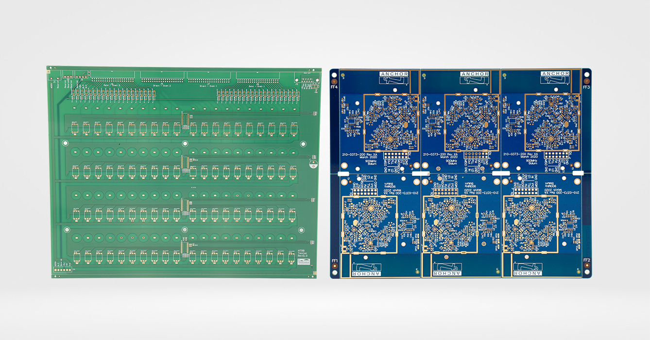
FR4’s processability is a key reason for its widespread adoption. Manufacturers must optimize parameters to ensure laminate integrity, dimensional accuracy, and consistent performance:
Lamination: The process of bonding glass fiber layers with epoxy resin under heat and pressure. Typical parameters include press temperatures of 170–190°C, pressures of 200–400 psi (1.4–2.8 MPa), and cycle times of 60–90 minutes. These settings vary by resin system—high-Tg FR4 often requires longer cure times to achieve full cross-linking of the epoxy.
Drilling: FR4’s hardness requires carbide drill bits for small vias (≤0.1 mm) to avoid burring or delamination. Drill speeds range from 20,000–60,000 RPM, with feed rates of 0.1–0.3 mm/rev. Coolant is essential to prevent resin softening from friction-generated heat.
Routing: CNC routers shape the PCB outline with tolerances of ±0.05 mm for standard designs and ±0.025 mm for precision applications (e.g., RF modules). Router bit sharpness is critical to avoid chipping the laminate edges.
Surface Preparation: Desmearing (chemical or plasma treatment) removes resin smears from drilled holes, ensuring reliable copper plating. Micro-etching (e.g., with sulfuric acid) roughens the copper surface to improve adhesion of solder mask and surface finishes.
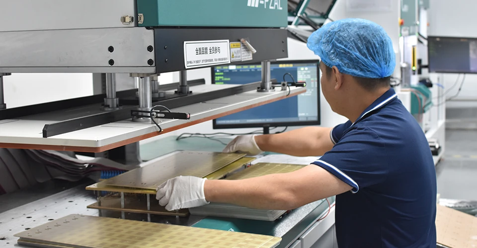
FR4 materials and finished PCBs must adhere to global standards to ensure interoperability, safety, and reliability. Key specifications include:
IPC-4101: The primary standard for base materials, classifying FR4 into types based on performance. Type 1 covers general-purpose FR4, while Type 2 includes high-performance variants with enhanced thermal or electrical properties. IPC-4101/21 specifies test methods for evaluating properties like dielectric strength, peel strength, and thermal stability.
UL 94: Defines flame retardancy ratings. FR4 is typically rated UL94 V-0, meaning it extinguishes within 10 seconds of removing an ignition source and does not drip flaming particles. This is mandatory for consumer electronics, medical devices, and industrial equipment.
IEC 61249: Covers materials for printed boards, including FR4, with a focus on environmental performance (e.g., RoHS compliance). It restricts hazardous substances like lead, cadmium, and hexavalent chromium, ensuring FR4 PCBs meet global environmental regulations.
MIL-PRF-31032: A military specification for high-reliability PCBs, often requiring FR4 with tight tolerances, high Tg, and enhanced thermal cycling resistance for aerospace and defense applications.
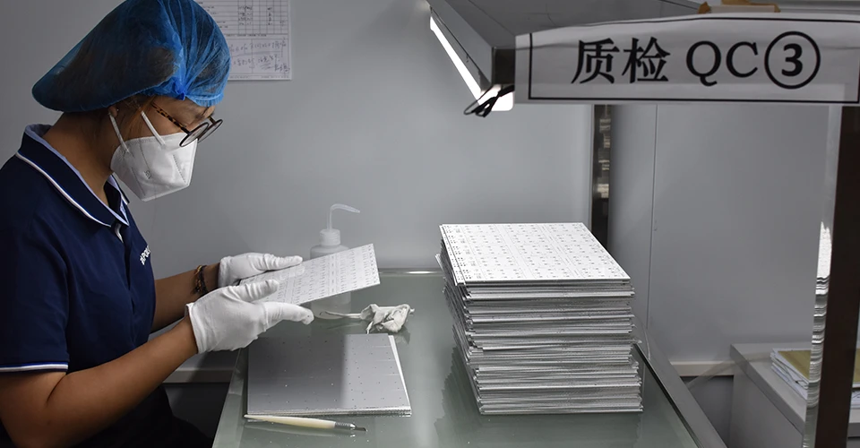
Rigorous testing ensures FR4 materials meet specification and perform reliably in end applications. Common tests include:
Thermal Cycling: Exposing PCBs to -55°C to +125°C for 28 cycles (per IPC-TM-650 2.6.7) to evaluate resistance to repeated temperature changes. This identifies delamination or via cracking risks.
Solder Float Test: Immersing the laminate in a 260°C solder bath for 10 seconds (IPC-TM-650 2.4.13) to check for blistering or delamination, ensuring compatibility with lead-free soldering.
Flammability Testing: UL 94 vertical burn tests confirm the V-0 rating, with samples required to self-extinguish quickly without propagating flame.
Moisture Resistance: Pressure cooker tests (PCT) expose FR4 to high temperature (121°C) and humidity (100%) under pressure (2 atm) for 24–96 hours, accelerating moisture absorption to evaluate long-term reliability in humid environments.
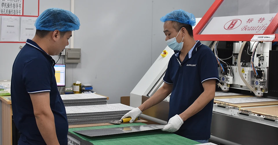
FR4’s versatility makes it suitable for most PCB applications, but understanding its limitations is key to selecting the right material:
Consumer Electronics: Smartphones, laptops, and TVs use standard FR4 for its cost-effectiveness and moderate performance.
Industrial Control: Motor drives, PLCs, and sensors often require mid-Tg FR4 to withstand 125°C operational temperatures.
Telecommunications: Routers and base stations use low-Dk FR4 to minimize signal loss in high-frequency (1–10 GHz) applications.
Automotive: Infotainment systems and cabin electronics use mid-Tg FR4, while underhood components may require high-Tg, low-CTE variants to resist engine heat.
Limitations: FR4 is unsuitable for extreme environments, such as aerospace PCBs exposed to -55°C to +125°C cycling (where polyimide or ceramic laminates perform better) or high-power applications (e.g., 100W+ LEDs) requiring metal-core PCBs for superior heat dissipation.
The FR4 family continues to evolve to meet emerging demands:
Eco-Friendly FR4: Bromine-free flame retardants (e.g., phosphorus-based additives) address concerns about brominated compounds, meeting stricter environmental regulations in regions like the EU.
High-Frequency FR4: Modified with low-Dk resins and optimized glass weaves, these variants (e.g., Rogers RO4000 series, though not pure FR4) target 5G and radar applications with Dk values as low as 3.3.
Thermally Enhanced FR4: Ceramic-filled formulations (e.g., Panasonic R-1787) boost thermal conductivity to 0.8–1.0 W/m·K, reducing the need for heat sinks in mid-power devices.
The FR4 PCB material specification sheet is an indispensable tool for engineers and manufacturers, bridging theoretical properties with practical application. By understanding its electrical, mechanical, and thermal behavior, stakeholders can select the right FR4 variant, optimize design parameters, and ensure PCB reliability. As technology advances, FR4 continues to adapt—remaining the material of choice for the majority of PCB applications while pushing boundaries in performance and sustainability.
Related Articles
Top PCB Manufacturers Near You | High-Quality PCB & PCBA Solutions
Countersink Holes in FR4 PCB: Engineering Principles for Precision Assembly
FR4 PCB Manufacturer | High Tg & Reliable PCB Material FR4 Solutions
Countersink Holes in FR4 PCB: Engineering Principles for Precision Assembly
LED Lighting FR4 PCB: Technical Foundations for Illumination Systems
FR4 PCB Manufacturer for Prototype and Mass Production
Tg170 FR4 PCB Datasheet PDF: A Detailed Exploration of High-Tg Laminate Specifications
Countersink Holes in FR4 PCB: Engineering Principles for Precision Assembly
HDI Blind/Buried Vias FR4 PCB: High-Density Interconnect Solutions for Advanced Electronics

Got project ready to assembly? Contact us: info@apollopcb.com


We're not around but we still want to hear from you! Leave us a note:

Leave Message to APOLLOPCB
