-
- PCB TYPE
- PRINTED CIRCUIT BOARD PROTOTYPE ALUMINUM PRINTED CIRCUIT BOARD R&F PCB FPC HIGH FREQUENCY PCB HIGH-TG PCB HEAVY COPPER PCB HDI PCB PCB FOR LIGHTING METAL CORE PCB
time:Aug 05. 2025, 09:14:53
In the vast ecosystem of printed circuit board (PCB) materials, FR4 PCB stands as the most widely used substrate, underpinning everything from simple consumer gadgets to complex industrial machinery. FR4, a glass-reinforced epoxy laminate, has earned its prominence through a unique combination of electrical insulation, mechanical durability, thermal resilience, and cost-effectiveness. Unlike specialized materials tailored for niche applications, FR4 PCB balances performance across multiple criteria, making it the default choice for over 90% of PCB designs. This article explores the technical foundations of FR4 PCB, from its material structure and key properties to its manufacturing processes and diverse applications, highlighting why it remains indispensable in the ever-evolving electronics industry.
FR4 PCB refers to printed circuit boards fabricated using FR4 laminate as the base material. FR4 itself is a thermoset composite classified as a copper-clad laminate (CCL), where "FR" denotes "flame-retardant"—a critical safety feature that prevents sustained combustion. This distinguishes it from non-flame-retardant predecessors like G10, which lack the fire-resistant additives essential for modern electronics.
At its simplest, an FR4 PCB consists of layers of FR4 laminate bonded together with copper traces etched into circuit patterns. The number of layers can range from 1 (single-sided) to over 40 (high-layer-count), with each layer contributing to the board’s functionality. What sets FR4 PCB apart is its adaptability: it can be tailored with varying copper thicknesses, laminate grades, and surface finishes to meet specific design requirements, from low-cost toys to high-reliability medical devices.
The term "FR4" is often used interchangeably with the laminate and the PCB itself, but it’s important to note that the PCB incorporates additional elements like solder mask, silkscreen, and surface finishes that enhance performance and manufacturability—elements not present in the raw laminate.
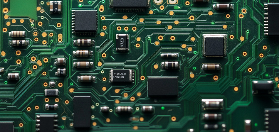
An FR4 PCB’s performance is determined by the composition of its core laminate, which combines four key components working in synergy:
Epoxy Resin Matrix: The binding agent that holds the laminate together, providing electrical insulation and chemical resistance. Most FR4 PCBs use bisphenol-A-based epoxy resins, though modified versions (e.g., with novolac hardeners) are used for high-temperature grades. The resin undergoes a curing process at 170–190°C, forming a cross-linked polymer network that gives the material its rigidity.
Glass Fiber Reinforcement: E-glass fibers woven into fabrics (e.g., 1080, 2116, 7628) provide mechanical strength and dimensional stability. The weave density affects properties like flexural strength and moisture absorption: finer weaves (1080) offer better surface smoothness for fine-pitch components, while thicker weaves (7628) enhance rigidity for large boards.
Copper Foil: Thin sheets of copper (0.5–4 oz) bonded to the laminate surface, forming the conductive traces. Electrodeposited (ED) copper, with a rough surface for strong adhesion, is standard, while rolled copper—smoother and more ductile—is used for flexible-rigid PCBs or applications requiring fine-line etching.
Additives: Flame retardants (e.g., brominated compounds or phosphorus-based alternatives) to meet UL94 V-0 standards; coupling agents (silanes) to strengthen the bond between glass fibers and resin; and fillers (e.g., silica) in specialized grades to reduce thermal expansion.
These components are layered and pressed together during manufacturing, creating a unified structure that balances the resin’s insulating properties with the glass’s mechanical strength and copper’s conductivity.
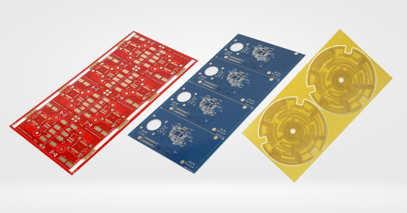
FR4 PCB’s widespread adoption stems from its favorable combination of electrical, mechanical, and thermal properties:
Electrical Insulation: The epoxy resin provides excellent dielectric properties, with a dielectric constant (Dk) of 4.2–4.8 at 1 MHz and a dissipation factor (Df) ≤0.02. This ensures minimal signal loss in low-to-moderate frequency applications (up to 10 GHz), making it suitable for most consumer and industrial electronics.
Mechanical Strength: Tensile strength of ≥400 MPa and flexural strength of ≥500 MPa allow FR4 PCBs to withstand manufacturing stresses (e.g., drilling, routing) and operational loads (e.g., vibration in automotive applications). This strength is anisotropic—higher along the fiber direction—guiding designers to align critical components accordingly.
Thermal Performance: A glass transition temperature (Tg) of 130–140°C for standard grades, ensuring stability in ambient temperatures up to 100°C. High-Tg variants (Tg ≥170°C) extend this range, making them suitable for underhood automotive or industrial oven applications.
Cost-Effectiveness: Compared to specialized materials like PTFE (for high-frequency) or ceramic (for high-temperature), FR4 PCB offers a lower price point while meeting the needs of most applications. This cost advantage is amplified in high-volume production, where economies of scale further reduce per-unit costs.
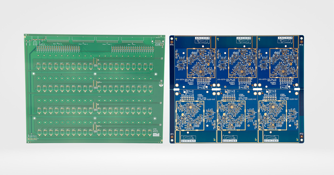
Producing an FR4 PCB involves a series of precise steps that transform raw laminate into a functional circuit board:
Cutting and Shearing: Large laminate sheets are cut to the PCB’s final dimensions, with extra margin for processing.
Drilling: Holes (vias, tooling holes) are drilled using CNC machines with carbide bits, ranging from 0.1 mm (microvias) to 5 mm (through-holes). This connects layers in multi-layer PCBs.
Plating: Through-holes are plated with copper to create electrical connections between layers, using processes like electroless copper deposition followed by electrolytic plating.
Imaging and Etching: Photoresist is applied, exposed to UV light through a circuit pattern mask, and developed to protect copper traces. Unprotected copper is etched away using ferric chloride or ammonium persulfate, leaving the desired circuit.
Solder Mask Application: A polymer coating (solder mask) is applied to insulate copper traces, leaving only pads exposed for soldering. This prevents short circuits and protects against environmental damage.
Surface Finishing: The exposed pads are coated with finishes like HASL (hot air solder level), ENIG (electroless nickel immersion gold), or OSP (organic solderability preservative) to ensure solderability and corrosion resistance.
Silkscreen Printing: Text, logos, and component outlines are printed on the solder mask using ink, aiding in assembly and troubleshooting.
Electrical Testing: PCBs undergo continuity and isolation tests to detect shorts or opens, with automated optical inspection (AOI) checking for physical defects.
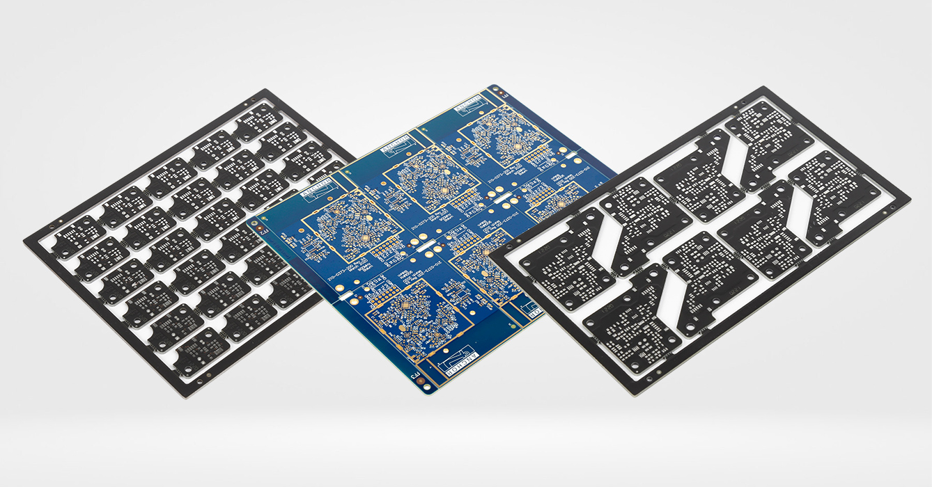
Designing an FR4 PCB requires balancing performance, manufacturability, and cost, with key considerations including:
Layer Stackup: Determining the number of layers and their arrangement (e.g., signal, power, ground planes) to minimize crosstalk and optimize signal integrity. Multi-layer FR4 PCBs use ground planes to reduce EMI and provide shielding.
Trace Width and Spacing: Governed by current-carrying capacity (wider traces for higher current) and signal frequency (narrower spacing for high-speed signals, within manufacturability limits). Standard FR4 PCBs can achieve trace widths/spacing as small as 0.1 mm with modern processes.
Via Design: Through-hole, blind, or buried vias connect layers, with size and placement affecting signal integrity. Microvias (≤0.15 mm) in HDI (high-density interconnect) FR4 PCBs enable miniaturization for smartphones and wearables.
Copper Thickness: Thicker copper (2–4 oz) is used for power PCBs to handle high current, while thinner copper (0.5 oz) is preferred for fine-line traces in dense designs.
Thermal Management: For high-power components, FR4 PCBs can incorporate heat sinks, thermal vias (filled with conductive epoxy), or metal cores (hybrid designs) to dissipate heat—though thermal conductivity remains lower than metal-core PCBs.
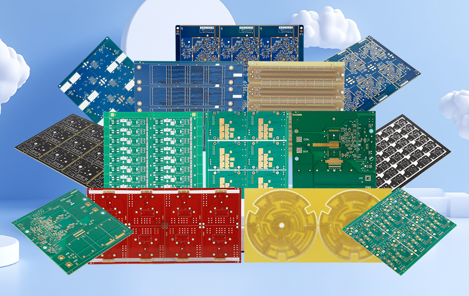
FR4 PCBs are available in multiple grades, each optimized for specific environments:
Standard FR4: Tg 130–140°C, suitable for consumer electronics (e.g., TVs, routers) operating in 0–70°C environments. It offers the best balance of cost and performance for non-critical applications.
High-Tg FR4: Tg ≥170°C, designed for high-temperature environments like automotive underhood (up to 150°C) or industrial ovens. The modified resin system resists softening at elevated temperatures, reducing warpage.
Low-Cost FR4: Using thinner glass weaves and lower resin quality, this grade targets budget applications like toys or disposable electronics, where performance margins are less critical.
High-Reliability FR4: Meets aerospace or military standards (e.g., MIL-PRF-31032), with tighter tolerances, enhanced moisture resistance, and improved thermal cycling performance. These undergo rigorous testing, including thermal shock and vibration.
Halogen-Free FR4: Uses phosphorus-based flame retardants instead of bromine, complying with strict environmental regulations (e.g., EU RoHS 2.0) for applications in healthcare and automotive.
The surface finish of an FR4 PCB protects exposed copper pads, ensuring solderability and preventing oxidation. Common options include:
HASL (Hot Air Solder Level): A layer of tin-lead or lead-free solder applied via immersion, then leveled with hot air. Cost-effective but unsuitable for fine-pitch components due to uneven thickness.
ENIG (Electroless Nickel Immersion Gold): A thin layer of gold over nickel, offering excellent solderability, flatness, and corrosion resistance. Ideal for high-reliability applications like medical devices and smartphones.
OSP (Organic Solderability Preservative): A thin organic coating that protects copper from oxidation. Low-cost and suitable for lead-free soldering but requires careful storage to maintain effectiveness.
Immersion Silver/Tin: Alternatives to ENIG with good solderability and cost, used in consumer electronics and industrial equipment.
The choice depends on factors like shelf life, soldering process, and cost, with ENIG being the gold standard (pun intended) for high-performance FR4 PCBs.
FR4 PCB’s versatility makes it ubiquitous across industries:
Consumer Electronics: Smartphones, laptops, TVs, and wearables rely on FR4 PCBs for their balance of cost, size, and performance. High-density FR4 PCBs with HDI technology enable the miniaturization of these devices.
Automotive: Infotainment systems, sensors, and lighting controls use standard FR4 PCBs, while underhood components (e.g., ECUs) use high-Tg variants to withstand temperature extremes.
Industrial: Motor drives, PLCs, and robotics use FR4 PCBs for their mechanical robustness and resistance to vibration. Flame retardancy is critical here, as industrial environments often have strict safety codes.
Medical: Diagnostic equipment, pacemakers, and imaging devices use high-reliability FR4 PCBs with ENIG finishes, ensuring biocompatibility and long-term performance.
Aerospace: Non-critical avionics (e.g., in-flight entertainment) use qualified FR4 PCBs, though mission-critical systems may require specialized materials like polyimide for extreme conditions.
To ensure reliability, FR4 PCBs undergo rigorous testing:
Electrical Testing: Continuity checks (to verify connections) and isolation tests (to detect shorts) using flying probe or bed-of-nails testers.
Thermal Cycling: Exposure to -40°C to +125°C for 100–1,000 cycles to test solder joint and via integrity, critical for automotive and industrial applications.
Mechanical Testing: Flexure tests to ensure the PCB withstands bending during assembly, and peel strength tests to verify copper adhesion.
Environmental Testing: Humidity testing (85°C/85% RH) to check for delamination, and salt spray testing for corrosion resistance in marine or industrial environments.
X-Ray Inspection: Used to inspect hidden features like BGA solder joints and via fill, ensuring no voids or defects.
While versatile, FR4 PCB has limitations that guide material selection:
High-Frequency Performance: Above 10 GHz, FR4’s Dk stability degrades, making it unsuitable for 5G millimeter-wave or radar applications, where PTFE-based laminates (e.g., Rogers) perform better.
Extreme Temperatures: Continuous operation above 150°C can cause standard FR4 to soften, requiring high-Tg FR4 or polyimide-based PCBs for aerospace or downhole drilling.
Flexibility: FR4 is rigid, so flexible PCBs use polyimide substrates for applications like wearable sensors or foldable displays.
Thermal Conductivity: With 0.2–0.3 W/m·K, FR4 PCB struggles with high-power components (e.g., 100W+ LEDs), where metal-core PCBs (MCPCBs) or ceramic substrates are preferred.
Innovation continues to expand FR4 PCB’s capabilities:
HDI (High-Density Interconnect): Microvias and sequential lamination enable finer trace widths (≤50 μm) and higher component density, critical for 5G devices and IoT sensors.
Sustainable Materials: Bio-based epoxy resins derived from plant oils reduce environmental impact, while recycled glass fibers lower carbon footprints—aligning with EU and US sustainability goals.
Thermally Enhanced FR4: Ceramic-filled laminates (e.g., Panasonic R-1787) boost thermal conductivity to 0.8 W/m·K, bridging the gap between standard FR4 and MCPCBs for mid-power applications.
3D-Printed FR4 PCBs: Experimental processes use FR4-compatible inks to print 3D structures, enabling complex geometries like integrated heat sinks or conformal antennas.
FR4 PCB remains the cornerstone of modern electronics, offering an unrivaled balance of performance, versatility, and cost. From its humble origins as a flame-retardant laminate to its current role in enabling cutting-edge technologies like 5G and IoT, FR4 PCB has proven its adaptability. While specialized materials will always have their place, FR4 PCB’s ability to meet the needs of 90% of applications ensures it will remain indispensable for decades to come. As manufacturing processes advance and material science evolves, FR4 PCB will continue to push boundaries, solidifying its position as the most trusted substrate in electronics.

Got project ready to assembly? Contact us: info@apollopcb.com


We're not around but we still want to hear from you! Leave us a note:

Leave Message to APOLLOPCB
