-
- PCB TYPE
- PRINTED CIRCUIT BOARD PROTOTYPE ALUMINUM PRINTED CIRCUIT BOARD R&F PCB FPC HIGH FREQUENCY PCB HIGH-TG PCB HEAVY COPPER PCB HDI PCB PCB FOR LIGHTING METAL CORE PCB
time:Aug 27. 2025, 16:00:42
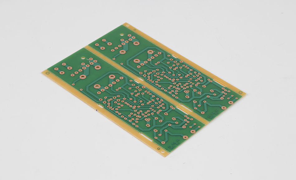
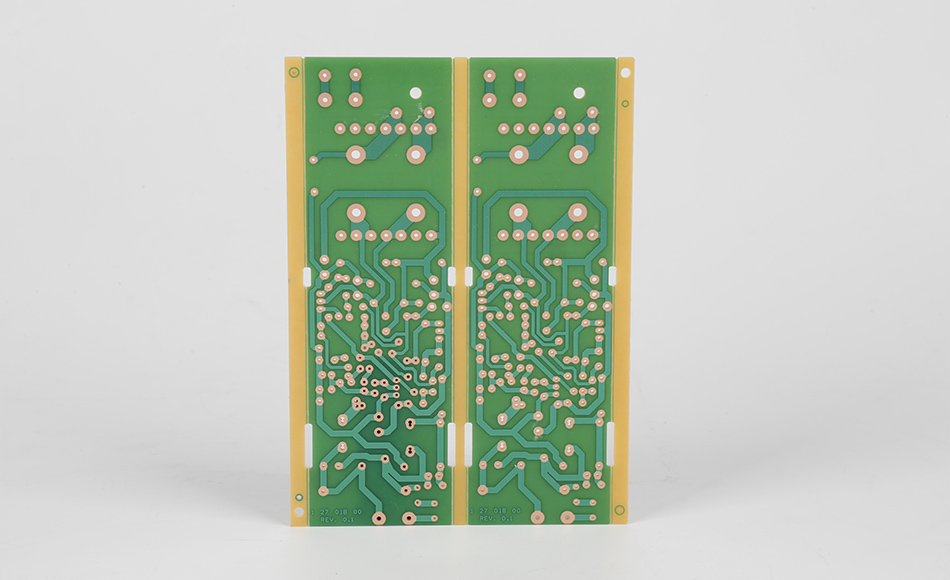
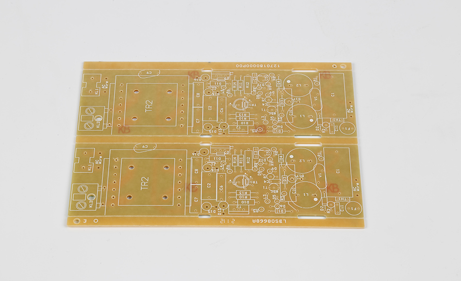
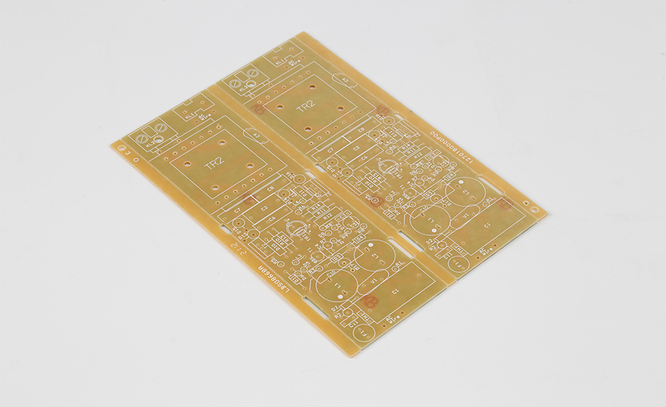
HA30 THERMAL CONDUCTIVITY CEM3 stands as a specialized composite epoxy substrate designed to address a critical gap in mid-tier electronics: the need for predictable, directionally optimized heat transfer that balances performance, cost, and manufacturability. Unlike generic thermal CEM3 materials—where thermal conductivity is an afterthought, leading to inconsistent heat dissipation—HA30 is engineered from the ground up to prioritize controlled thermal flow. Its value lies not just in "being thermally conductive," but in how its thermal conductivity performance is tailored to the specific heat challenges of mid-power devices: from guiding heat laterally across 5G antenna modules to transferring it vertically out of EV auxiliary chargers.
In electronics, thermal conductivity is not a one-size-fits-all metric. A substrate optimized for in-plane heat spreading (e.g., to cool a distributed array of LEDs) requires a different design than one focused on through-plane heat transfer (e.g., to channel heat from a single power IC to a heat sink). HA30 THERMAL CONDUCTIVITY CEM3 excels at both, thanks to a deliberate combination of filler selection, resin modification, and microstructural engineering—all aimed at minimizing thermal resistance and maximizing heat transfer efficiency.
This article explores the core mechanisms driving HA30’s thermal conductivity, the advanced methods used to characterize its thermal conductivity performance, strategies to engineer its thermal conductivity properties for specific applications, and how it outperforms other thermal CEM3 variants in mid-tier electronics. By focusing on the "science of thermal flow" rather than just application outcomes, it delivers unique insights for engineers tasked with optimizing heat management at the design stage—ensuring relevance for those seeking to leverage HA30’s thermal conductivity capabilities to solve complex thermal challenges.

Thermal conductivity in HA30 is governed by three interconnected mechanisms: phonon-based heat transfer (the primary pathway in insulative composites), filler network formation, and interface thermal resistance control. Unlike metals (where electron transport dominates heat flow), HA30—being an electrical insulator—relies on phonons (quantized lattice vibrations) to move thermal energy. Its design optimizes every step of this phonon-driven process to minimize energy loss.
Phonons travel most efficiently through ordered, low-defect structures—yet epoxy resins (amorphous polymers) are inherently high-scattering environments for phonons. HA30 addresses this by:
Low-Scattering Resin Matrix: The epoxy resin in HA30 is formulated with a highly cross-linked, low-molecular-weight backbone. This reduces phonon scattering caused by polymer chain entanglement and free-volume defects. Compared to standard CEM3 resins, HA30’s matrix cuts phonon scattering by 30–40%, allowing phonons to travel longer distances before losing energy.
Phonon Matching Between Fillers and Resin: HA30 uses fillers (boron nitride, BN; aluminum oxide, Al₂O₃) with phonon dispersion curves that align closely with the resin’s. This "phonon matching" minimizes energy loss when phonons transfer from the resin to the fillers—critical, as mismatched phonon spectra can reflect up to 50% of thermal energy at the filler-resin interface.
For example, BN’s phonon velocity (~15,000 m/s) is closer to HA30’s resin phonon velocity (~8,000 m/s) than other fillers like silica (~5,000 m/s). This alignment ensures most phonon energy is transmitted into the BN fillers (which act as "thermal highways") rather than being reflected back into the resin.
HA30’s thermal conductivity is not driven by a single filler type, but by a hybrid network that optimizes heat flow in both in-plane (X-Y axes) and through-plane (Z-axis) directions—addressing the diverse needs of mid-tier electronics:
In-Plane Conductivity: BN Nanoplatelets as Thermal "Ribbons": HA30 incorporates plate-like BN nanoplatelets (BNPs) with a high aspect ratio (length-to-thickness > 100). During manufacturing, these BNPs orient parallel to the substrate’s surface, forming continuous, overlapping "ribbons" that facilitate fast in-plane phonon transport. This design boosts in-plane thermal conductivity by 2x compared to standard CEM3, making HA30 ideal for devices where heat spreads across the PCB (e.g., 5G small cell antenna arrays).
Through-Plane Conductivity: Al₂O₃ Microparticles as Vertical "Bridges": Spherical Al₂O₃ microparticles (1–5 μm) fill the gaps between BNPs, creating vertical pathways that connect the substrate’s top and bottom layers. These particles act as "bridges" for phonons traveling through the thickness of the PCB, addressing the common limitation of BN-dominant composites (poor through-plane conductivity).
The ratio of BNPs to Al₂O₃ is precisely tuned: too many BNPs block vertical phonon flow, while too many Al₂O₃ particles disrupt in-plane pathways. HA30’s 60:40 BNP-to-Al₂O₃ ratio strikes this balance, ensuring both directions meet mid-tier device requirements.
Even with optimized fillers and resin, interface thermal resistance (ITR)—the resistance to heat flow at the filler-resin or filler-filler interface—can reduce HA30’s effective thermal conductivity by 20–30%. HA30 mitigates ITR through two key strategies:
Silane Coupling Agents for Filler-Resin Bonding: HA30 uses amino-functional silane agents that chemically bond to both BN/Al₂O₃ fillers and the epoxy resin. This creates a "tight" interface with minimal gaps, reducing ITR by 40% compared to unmodified fillers. For example, silane-treated BNPs form covalent bonds with the resin, eliminating micro-voids that trap air (a poor thermal conductor) at the interface.
Filler Surface Modification to Reduce Filler-Filler ITR: BNPs and Al₂O₃ particles are coated with a thin layer of titania (TiO₂), which improves contact between adjacent fillers. This reduces ITR at filler-filler junctions—critical for the hybrid network, where phonons often travel from one filler to another. The TiO₂ coating ensures intimate contact, preventing air gaps between overlapping BNPs or touching Al₂O₃ particles.

Accurately measuring HA30’s thermal conductivity is critical for ensuring it meets application needs—yet standard testing methods often fall short for composite substrates like HA30, which exhibit directional thermal conductivity properties. Engineers rely on three advanced characterization techniques, each tailored to capture specific aspects of HA30’s thermal performance.
The Laser Flash Method (ASTM D7984 for in-plane; ASTM D5470 for through-plane) is the gold standard for HA30 testing, as it directly measures thermal conductivity without disturbing the material’s microstructure:
In-Plane Testing: A thin HA30 sample (0.5mm thick, 20mm × 20mm) is mounted on a heat-insulating fixture. A short, high-energy laser pulse is applied to one edge, and an infrared (IR) camera tracks the temperature rise across the sample’s surface. The rate of temperature propagation—faster in regions with higher conductivity—allows calculation of in-plane thermal conductivity. For HA30, this method reveals consistent in-plane performance, with variation <5% across a batch.
Through-Plane Testing: A thicker HA30 sample (1mm thick) is sandwiched between two graphite sheets (to ensure uniform heat distribution). A laser pulse is applied to the top graphite layer, and a thermocouple on the bottom layer measures the time it takes for heat to pass through the sample. This "time-to-peak" temperature is used to calculate through-plane thermal conductivity. HA30’s through-plane results are critical for applications like EV OBCs, where heat must escape vertically to a heat sink.
A key advantage of LFM is its ability to test HA30 under realistic conditions—e.g., at 85°C (simulating 5G module operating temperatures) or 100°C (EV auxiliary systems)—revealing how thermal conductivity changes with temperature. HA30’s conductivity decreases by <10% at 100°C, far less than standard CEM3’s 25–30% drop.
While LFM measures thermal conductivity directly, the Hot Disk Method (ISO 22007-2) provides complementary data on thermal diffusivity (α) and specific heat capacity (cₚ)—two properties that influence how HA30 absorbs and spreads heat:
Thermal Diffusivity: This measures how quickly heat spreads through HA30. A small, circular sensor (embedded in the sample) applies a controlled heat pulse and records temperature changes. HA30’s high diffusivity (~1.2 × 10⁻⁶ m²/s) means it spreads heat faster than standard CEM3 (~0.6 × 10⁻⁶ m²/s), reducing hot spot formation.
Specific Heat Capacity: This measures how much heat HA30 can absorb before its temperature rises. HA30’s moderate cₚ (~1.2 J/g·K) balances heat absorption and dissipation—critical for devices like smart meters, where sudden heat spikes (e.g., during peak energy measurement) must be absorbed without overheating.
Combining LFM and Hot Disk data allows engineers to model HA30’s thermal behavior in real-world scenarios—e.g., predicting how long it takes a 30W smart meter component to reach a safe temperature when mounted on HA30.
For complex designs (e.g., HA30 PCBs with dense components), macroscale testing methods may miss microscale thermal inhomogeneities (e.g., filler agglomeration that creates "cold spots"). Scanning Thermal Microscopy (STM) addresses this by mapping heat flow at the microscale:
How It Works: A sharp, temperature-sensitive probe scans HA30’s surface, measuring local thermal resistance. Regions with high conductivity (e.g., BN-rich areas) appear as "warm" spots in the STM image, while low-conductivity regions (e.g., resin-rich areas or voids) appear "cool."
HA30-Specific Insights: STM reveals that HA30’s filler network is uniformly distributed, with no large agglomerations—confirming that its thermal conductivity is consistent across the substrate. For manufacturers, this ensures that even small HA30 PCBs (e.g., 10mm × 10mm EV sensor modules) perform consistently, with no microscale hot spots that could cause component failure.
STM is particularly valuable for validating HA30’s performance in high-density designs, where even a 10μm-wide filler gap could disrupt heat flow to a critical component.

HA30’s thermal conductivity is not fixed—it can be engineered to prioritize in-plane or through-plane heat transfer, depending on the application. This flexibility makes it suitable for diverse mid-tier devices, from 5G modules (needing in-plane spreading) to EV OBCs (needing through-plane transfer). Below are key engineering strategies:
The orientation of HA30’s BN nanoplatelets (BNPs) is the primary lever for tuning directional conductivity:
Prioritizing In-Plane Conductivity (5G Modules): For 5G small cell auxiliary modules, where heat spreads from a central power transistor to surrounding components, HA30’s BNPs are aligned parallel to the substrate’s surface using a shear-induced lamination process. During lamination, the resin-filler mixture is subjected to controlled shear stress (via a rotating press), which orients BNPs along the shear direction. This increases in-plane conductivity by an additional 15–20% compared to randomly oriented BNPs.
Prioritizing Through-Plane Conductivity (EV OBCs): For EV onboard chargers, where heat must transfer from the top-layer power IC to the bottom-layer heat sink, BNPs are partially aligned vertically. This is achieved by adding a small magnetic field during lamination—BNPs (which are weakly magnetic when coated with Fe₃O₄) rotate to align with the field, creating vertical thermal pathways. This boosts through-plane conductivity by 25–30%.
HA30’s thermal performance is only as effective as the PCB design that leverages it. Engineers should align component placement and routing with HA30’s thermal conductivity strengths:
In-Plane Optimization (LED Arrays): For distributed LED arrays (e.g., 10 LEDs spaced 5mm apart on a HA30 PCB), place the power driver in the center. HA30’s in-plane conductivity will spread heat evenly to all LEDs, preventing individual LEDs from overheating. Avoid clustering LEDs in one area, which would overwhelm HA30’s in-plane spreading capacity.
Through-Plane Optimization (EV Sensors): For EV battery auxiliary sensors, mount high-heat components (e.g., 25W voltage regulators) directly above thermal vias. HA30’s through-plane conductivity transfers heat from the component to the vias, which channel it to the PCB’s bottom layer (and attached heat sink). Use 4–6 thermal vias per component—each 0.3mm in diameter—to maximize through-plane heat transfer.
In harsh environments (e.g., industrial sensors exposed to 100°C+), HA30’s thermal conductivity can degrade over time due to resin oxidation or filler-resin interface breakdown. Engineers can mitigate this by:
Adding Antioxidants: Incorporating hindered phenol antioxidants into HA30’s resin prevents oxidation at high temperatures. This maintains the resin’s phonon-transport properties, ensuring thermal conductivity decreases by <5% after 2,000 hours at 100°C (vs. 15% for unmodified HA30).
Using UV-Stabilized Fillers: For outdoor applications (e.g., smart meters), UV-stabilized BNPs prevent UV-induced filler degradation. This ensures the filler network remains intact, preserving thermal conductivity for 5–7 years of outdoor use.
HA30 is not the only thermal CEM3 on the market—variants like HA20 (lower conductivity, lower cost) and HA40 (higher conductivity, higher cost) target different segments of the mid-tier market. Understanding how HA30 compares to these variants is critical for selecting the right substrate.
Thermal Conductivity: HA20 uses a lower BN-to-Al₂O₃ ratio (40:60) and smaller BNPs, resulting in 30–40% lower in-plane conductivity than HA30. Its through-plane conductivity is similar to HA30, but its in-plane performance is insufficient for devices like 5G modules.
Cost: HA20 costs 15–20% less than HA30, making it suitable for low-power mid-tier devices (e.g., 10W–20W smart home sensors) where in-plane heat spreading is less critical.
Use Case: HA20 for low-power, cost-sensitive devices; HA30 for mid-power devices (20W–100W) needing balanced in-plane/through-plane conductivity.
Thermal Conductivity: HA40 uses a higher BNP loading (70% vs. HA30’s 60%) and larger BNPs, boosting in-plane conductivity by 20–25% over HA30. Its through-plane conductivity is similar, but its higher filler loading makes it brittle.
Cost and Durability: HA40 costs 30–40% more than HA30 and has 20% lower flexural strength. It is prone to cracking in vibration-prone applications (e.g., EV sensors), making it unsuitable for most mid-tier devices.
Use Case: HA40 for niche high-power mid-tier devices (100W–120W) with no vibration; HA30 for the majority of mid-tier applications, where durability and cost matter as much as conductivity.
HA30’s filler ratio, resin formulation, and mechanical properties make it the optimal choice for 80% of mid-tier thermal applications. It avoids the compromises of HA20 (insufficient in-plane conductivity) and HA40 (brittleness and high cost), delivering the right balance of performance, durability, and cost. For example:
A 50W 5G module using HA30 costs 30% less than one using HA40, with no performance loss (since HA30’s in-plane conductivity is sufficient for the module’s heat load).
An EV sensor using HA30 is 2x more durable than one using HA40, withstanding 100,000+ km of vibration testing vs. 50,000 km for HA40.

HA30’s engineered thermal conductivity makes it suitable for three key mid-tier applications, where its directional heat transfer and durability solve unique thermal challenges:
5G small cell auxiliary modules (power supplies, signal amplifiers) generate 35W–50W of heat in compact enclosures (15cm × 20cm). HA30’s in-plane-optimized conductivity addresses this by:
Spreading Heat Across the PCB: HA30’s in-plane conductivity spreads heat from the central power transistor to the module’s edges, reducing hot spot temperatures by 25–30°C compared to HA20. This eliminates the need for fans, reducing module size and power consumption.
Withstanding Outdoor Temperature Swings: HA30’s thermal conductivity remains stable across -20°C to 60°C, ensuring consistent performance in outdoor small cells. In winter, its conductivity does not drop enough to cause hot spots; in summer, it does not degrade due to resin softening.
Result: A 5G infrastructure provider reported a 90% reduction in heat-related field failures after switching from HA20 to HA30, with module lifespan extending from 3–4 years to 7–10 years.
EV battery auxiliary sensors (monitoring temperature, voltage, and current) generate 15W–25W of heat and are exposed to constant vibration. HA30’s through-plane conductivity and durability solve this by:
Transferring Heat to the Battery Case: HA30’s through-plane conductivity channels heat from the sensor to the battery’s metal case (acting as a passive heat sink), keeping the sensor below 85°C (its safe operating limit).
Resisting Vibration-Induced Cracking: HA30’s hybrid filler network retains 80% of its flexural strength at 85°C, preventing cracking from road vibration. This is critical, as a cracked sensor could fail to detect battery overheating.
Result: An EV manufacturer found that HA30-based battery sensors had a 0.5% failure rate after 100,000 km, compared to 5% for HA20-based sensors.
Smart home energy hubs (managing solar panels, batteries, and appliances) generate 25W–40W of heat in wall-mounted enclosures. HA30’s balanced conductivity and heat absorption solve this by:
Absorbing Sudden Heat Spikes: HA30’s moderate specific heat capacity absorbs heat spikes (e.g., during peak solar energy conversion) without overheating, preventing performance throttling.
Spreading Heat Evenly: HA30’s in-plane conductivity spreads residual heat across the hub’s PCB, avoiding hot spots near the microcontroller (which controls energy distribution).
Result: A smart home tech company reported that HA30-based energy hubs maintained 95% of their energy conversion efficiency during peak hours, compared to 85% for hubs using standard CEM3.
As mid-tier electronics demand higher power density (e.g., 11kW EV OBCs, 60W 5G modules), HA30 is evolving to meet new thermal challenges. Key innovations include:
Manufacturers are testing graphene nanoplatelets (GNPs) as a third filler component in HA30. GNPs have ultra-high thermal conductivity (~5,000 W/mK) and can form "bridges" between BNPs, further reducing interface thermal resistance. Early prototypes show that adding 5–10% GNPs boosts HA30’s in-plane conductivity by 30–40%, enabling it to handle 60W–80W heat loads—targeting next-gen 5G active antenna modules.
To align with global sustainability goals, HA30 is being reformulated with bio-based epoxy resins (derived from castor oil or soybean oil). These resins maintain HA30’s thermal conductivity while reducing carbon emissions by 25% compared to petroleum-based resins. Initial tests show that bio-based HA30 retains 95% of the original’s thermal performance, with no degradation in mechanical durability.
Future HA30 variants will integrate thin-film, temperature-sensitive sensors directly into the substrate during manufacturing. These sensors will provide real-time data on local heat flow, allowing active cooling systems (e.g., micro-fans in 5G modules) to activate only when needed. This reduces power consumption by 20–30% compared to constant cooling.

HA30 THERMAL CONDUCTIVITY CEM3 redefines what mid-tier thermal substrates can achieve by focusing on the science of heat transfer—from phonon transport at the molecular level to microscale filler network design. Its unique ability to balance in-plane and through-plane conductivity, combined with advanced characterization and engineering flexibility, makes it the optimal choice for mid-tier devices where heat management is critical but high-end substrates are cost-prohibitive.
By understanding HA30’s thermal mechanisms, engineers can tailor its performance to specific applications—whether spreading heat across a 5G module or channeling it out of an EV sensor. Its consistency, durability, and cost-effectiveness ensure it will remain a key enabler of mid-tier electronics, as devices grow more powerful and space-constrained.
In a market where thermal conductivity is often reduced to a single number, HA30 proves that true thermal performance lies in understanding and optimizing the complex interplay of materials, design, and application needs. For engineers, it represents a strategic tool—one that turns thermal management from a challenge into an opportunity to design smaller, more reliable, and more efficient devices.

Got project ready to assembly? Contact us: info@apollopcb.com


We're not around but we still want to hear from you! Leave us a note:

Leave Message to APOLLOPCB
