-
- PCB TYPE
- PRINTED CIRCUIT BOARD PROTOTYPE ALUMINUM PRINTED CIRCUIT BOARD R&F PCB FPC HIGH FREQUENCY PCB HIGH-TG PCB HEAVY COPPER PCB HDI PCB PCB FOR LIGHTING METAL CORE PCB
time:Aug 19. 2025, 19:52:55
Precision Countersink CEM3 PCB Holes represent a critical detail in the manufacturing of Composite Epoxy Material-3 (CEM3) printed circuit boards, where even minor deviations can compromise the integrity of component assembly. Countersinking—creating a conical recess at the entrance of a hole—allows fasteners, connectors, or component leads to sit flush with the PCB surface, reducing mechanical stress, improving stability, and enhancing overall device reliability. In CEM3 PCBs, which balance affordability and performance for applications like consumer electronics and light industrial equipment, precision countersinking is particularly important: the material’s hybrid structure (non-woven glass core and woven glass layers) demands careful processing to avoid delamination, fraying, or uneven recesses. This article examines the techniques, challenges, quality standards, and applications of precision countersink CEM3 PCB holes, highlighting their role in ensuring seamless assembly and long-term functionality.
Countersinking is more than a cosmetic detail in CEM3 PCBs; it serves functional purposes that directly impact performance and durability:
When components or fasteners are mounted on a PCB, protruding leads or heads create uneven stress points that can warp the substrate over time, especially during thermal cycling. Precision countersinks allow these elements to sit flush, distributing stress evenly across the PCB surface. In CEM3 PCBs used in devices like small motor controllers, this prevents micro-cracks in the epoxy matrix or glass fibers, which could lead to electrical failures.
Countersinks act as guides during assembly, ensuring that cylindrical components (e.g., connectors, standoffs) are centered in their holes. This alignment is critical for maintaining electrical continuity—misaligned components can strain solder joints or create intermittent connections. For example, in a CEM3 PCB used in a printer’s sensor array, precisely countersunk holes ensure that optical sensors align perfectly with their lenses, preventing data inaccuracies.
In compact devices like wearable electronics or IoT sensors, every millimeter of space matters. Flush-mounted components, enabled by countersinks, reduce the overall profile of the PCB assembly, allowing for sleeker device designs. CEM3 PCBs, often used in such space-constrained applications, benefit significantly from this optimization.
A flush surface minimizes gaps where dust, moisture, or debris can accumulate, reducing the risk of corrosion or short circuits. In CEM3 PCBs deployed in humid environments (e.g., kitchen appliances), this protection is vital for maintaining long-term reliability.

CEM3’s unique material composition presents specific challenges that make precision countersinking more complex than in other substrates:
CEM3’s structure—non-woven glass core, woven glass outer layers, and epoxy resin—creates variations in density and hardness. The non-woven core is more porous and less rigid than the woven layers, which can cause uneven cutting: the countersink tool may remove material faster in the core, leading to a tapered or irregular recess. This inconsistency weakens the hole’s edge and increases the risk of delamination between layers.
Glass fibers in CEM3 are prone to fraying if cut with dull or improper tools. Frayed fibers can protrude into the countersink, preventing components from sitting flush and creating electrical insulation risks. Additionally, excessive heat or pressure during countersinking can break the bond between glass fibers and epoxy resin, causing delamination—a critical failure where layers separate, compromising mechanical and electrical performance.
The abrasive nature of glass fibers accelerates wear on countersink tools, especially high-speed steel (HSS) variants. Dull tools produce rough, uneven recesses and generate more heat, exacerbating delamination risks. This requires frequent tool changes or the use of specialized materials (e.g., carbide), increasing manufacturing costs if not managed properly.
CEM3 PCBs often require tight countersink tolerances (typically ±0.05mm for depth and angle) to match component specifications. Achieving this consistency across high-volume production runs is challenging due to material variations and tool wear, making rigorous quality control essential.
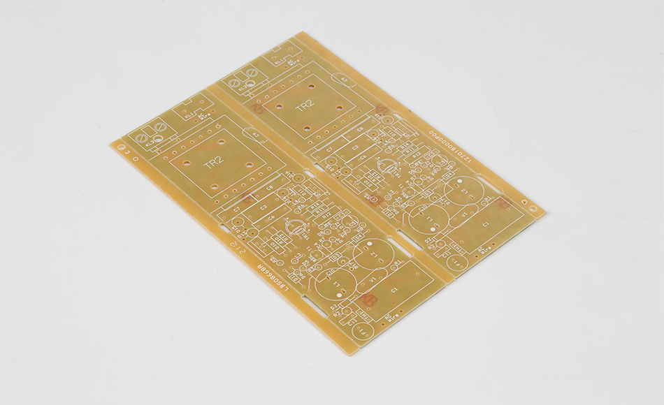
Manufacturers use specialized techniques to overcome CEM3’s challenges and achieve precise countersinks:
Carbide-Tipped Tools: Carbide’s hardness and wear resistance make it ideal for cutting glass-reinforced materials like CEM3. These tools maintain sharp edges longer, reducing fraying and ensuring consistent recesses.
Diamond-Coated Tools: For high-volume production, diamond-coated countersink tools offer superior durability, minimizing tool changes and maintaining precision across thousands of holes.
Variable Helix Designs: Tools with variable helix angles reduce cutting forces and heat buildup, lowering the risk of delamination. The helix design helps evacuate glass fiber debris, preventing clogging that can cause uneven cutting.
Spindle Speed: High speeds (30,000–50,000 RPM) with low feed rates minimize heat generation and fiber fraying. Slow, controlled feed rates allow the tool to shear fibers cleanly rather than tearing them.
Coolant Usage: Mist coolant systems apply a fine spray of lubricant during cutting, reducing friction and heat. This is particularly important for CEM3, as excessive heat can soften the epoxy resin, leading to burrs or uneven countersinks.
Pecking Cycles: For deeper countersinks, pecking—repeatedly advancing and retracting the tool—helps clear debris and prevents heat buildup, ensuring a clean, uniform recess.
Countersinking is often performed in sequence with drilling to ensure alignment:
Pilot Hole Drilling: A small-diameter pilot hole is drilled first to guide the countersink tool, reducing the risk of wandering (tool slippage that causes off-center recesses).
Countersinking: The tool is centered on the pilot hole and advanced to the desired depth and angle (typically 82° or 90°, matching standard fastener angles).
Final Hole Drilling: For through-holes, the full-diameter hole is drilled after countersinking to avoid damaging the countersink edge during the drilling process.
This sequence ensures that the countersink remains concentric with the final hole, critical for component alignment.
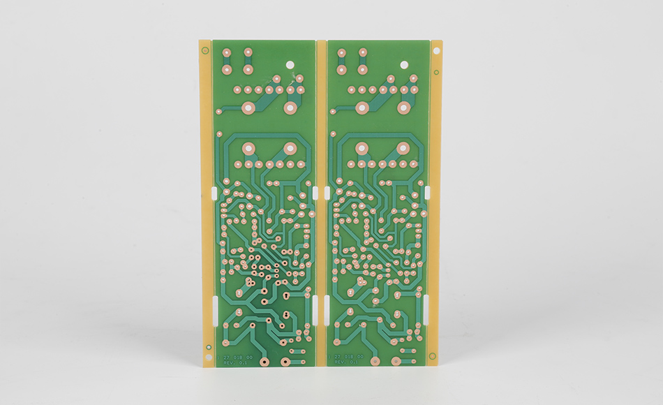
Maintaining consistency in countersink dimensions and surface quality is essential for CEM3 PCBs, requiring robust quality control measures:
Optical Coordinate Measuring Machines (CMMs): These systems use high-resolution cameras and laser scanners to measure countersink depth, angle, and diameter with micron-level precision. They compare measurements to CAD specifications, flagging deviations outside acceptable tolerances.
Machine Vision Systems: Integrated into production lines, these systems inspect countersinks for fraying, burrs, or uneven edges in real time, rejecting defective PCBs before they proceed to assembly.
For high-reliability applications (e.g., automotive electronics), periodic destructive testing is performed on sample PCBs:
Cross-Section Analysis: Cut sections of countersunk holes are examined under a microscope to check for delamination, fiber damage, or uneven resin distribution.
Pull-Test Validation: Fasteners are inserted into countersunk holes and pulled to measure retention strength, ensuring the countersink can withstand operational stresses.
Tool Wear Tracking: Sensors monitor spindle vibration and cutting force, alerting operators when tools become dull (indicated by increased vibration or force). This prevents quality degradation due to worn tools.
Statistical Process Control (SPC): Data from inspection systems is analyzed to identify trends (e.g., gradual increases in countersink depth), allowing for proactive adjustments to cutting parameters or tooling.
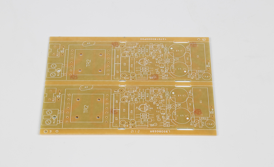
Precision countersinking is critical in CEM3 PCB applications where assembly accuracy and reliability are paramount:
Wearable Devices: Smartwatches and fitness trackers use CEM3 PCBs with countersunk holes for buttons and sensors. Flush mounting ensures comfort and prevents snags on clothing.
Home Appliances: Microwave control panels and coffee maker PCBs require countersunk holes for connectors and mounting screws, ensuring components withstand vibration during use.
Environmental Monitors: Sensors measuring humidity or gas levels use CEM3 PCBs with countersunk holes for protective covers. Flush mounting ensures the cover seals properly, preventing contamination.
Proximity Sensors: These devices rely on precise alignment between emitters and receivers, achieved through countersunk holes that center optical components.
Infotainment Systems: CEM3 PCBs in car stereos and navigation units use countersunk holes for connectors, ensuring reliable performance despite vehicle vibrations.
Climate Control Panels: Countersunk fasteners in these PCBs prevent loosening due to temperature fluctuations, maintaining consistent operation.
Portable Monitors: Blood pressure monitors and pulse oximeters use CEM3 PCBs with countersunk holes for battery contacts and display connectors, ensuring reliable operation in clinical settings.
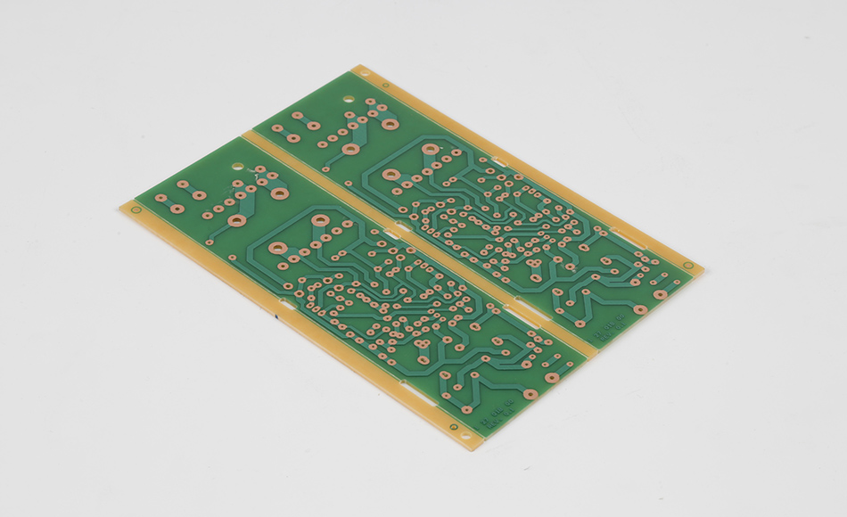
To achieve optimal results, manufacturers and designers should follow these guidelines:
Standardize Countersink Angles: Using common angles (82° or 90°) ensures compatibility with off-the-shelf tools and components, reducing costs and complexity.
Avoid Thin Substrates: CEM3 PCBs thinner than 1.0mm are prone to countersink breakthrough (the tool cutting through the opposite side). Designers should specify PCB thicknesses that accommodate countersink depth without compromising structural integrity.
Include Clearances: Adding a small clearance (0.1–0.2mm) between the countersink edge and copper traces prevents damage to conductive paths during cutting.
Using tools designed for glass-reinforced epoxies (e.g., carbide with sharp, polished flutes) minimizes fiber fraying and tool wear, ensuring consistent quality.
Post-Processing
Deburring—removing small metal or glass fiber projections from countersink edges—improves component fit and reduces the risk of insulation damage. For CEM3 PCBs, this is often done with abrasive brushes or ultrasonic cleaning to avoid damaging the substrate.
Advancements in manufacturing technology are enhancing precision and efficiency in CEM3 PCB countersinking:
Laser systems offer non-contact cutting, reducing mechanical stress on CEM3 substrates. They can achieve extremely tight tolerances and complex shapes, though high equipment costs currently limit their use to high-value applications.
Machine learning algorithms analyze real-time data from sensors and inspection systems to adjust cutting parameters (speed, feed rate) dynamically, optimizing countersink quality for variations in CEM3 material batches.
Robotic systems with automatic tool changers reduce downtime for tool changes, maintaining consistency across high-volume production runs and lowering costs.
Precision Countersink CEM3 PCB Holes are a small but critical detail that significantly impacts the performance, reliability, and manufacturability of CEM3-based devices. By addressing the unique challenges of CEM3’s hybrid structure through specialized tooling, optimized cutting parameters, and rigorous quality control, manufacturers ensure that countersinks enable flush component mounting, even stress distribution, and long-term stability. From consumer electronics to industrial sensors, these precision features play an essential role in creating devices that are both functional and durable. As manufacturing technologies advance, the ability to produce high-precision countersinks in CEM3 PCBs will only improve, further expanding the material’s utility in demanding applications where accuracy and cost-effectiveness are equally important.

Got project ready to assembly? Contact us: info@apollopcb.com


We're not around but we still want to hear from you! Leave us a note:

Leave Message to APOLLOPCB
